|
JET ENGINE
|
||||||||||||||||||||||||||||||||||||||||||||||||||||||||||||
|
HOME | BIOLOGY | FILMS | GEOGRAPHY | HISTORY | INDEX | MUSIC | SOLAR BOATS | SPORT | SPONSORS |
||||||||||||||||||||||||||||||||||||||||||||||||||||||||||||
|
A jet engine is an engine that discharges a fast moving jet of fluid to generate thrust in accordance with Newton's third law of motion. This broad definition of jet engines includes turbojets, turbofans, rockets and ramjets and water jets, but in common usage, the term generally refers to a gas turbine used to produce a jet of high speed exhaust gases for special propulsive purposes.
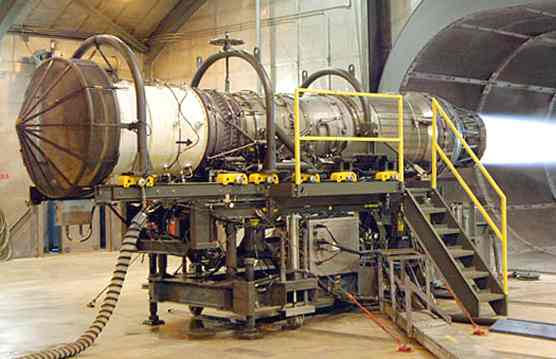
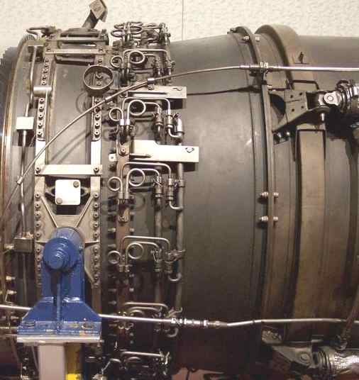
A Pratt and Whitney turbofan engine for the F-15 Eagle is tested at Robins Air Force Base, Georgia, USA.
History
Jet engines can be dated back to the first century AD, when Hero of Alexandria invented the aeolipile. This used steam power directed through two jet nozzles so as to cause a sphere to spin rapidly on its axis. So far as is known, it was never used for supplying mechanical power, and the potential practical applications of Hero's invention of the jet engine were not recognized. It was simply considered a curiosity.
Jet propulsion only literally and figuratively took off with the invention of the rocket by the Chinese in the 11th century. Rocket exhaust was initially used in a modest way for fireworks but gradually progressed to propel some quite fearsome weaponry; and there the technology stalled for hundreds of years.
The problem was that rockets are simply too inefficient to be useful for general aviation. Instead, by the 1930s, the piston engine in its many different forms (rotary and static radial, aircooled and liquid-cooled inline) was the only type of powerplant available to aircraft designers. This was acceptable as long as only low performance aircraft were required, and indeed all that were available.
However, engineers were beginning to realize conceptually that the piston engine was self-limiting in terms of the maximum performance which could be attained; the limit was essentially one of propeller efficiency. This seemed to peak as blade tips approached the speed of sound. If engine, and thus aircraft, performance were ever to increase beyond such a barrier, a way would have to be found to radically improve the design of the piston engine, or a wholly new type of powerplant would have to be developed. This was the motivation behind the development of the gas turbine engine, commonly called a "jet" engine, which would become almost as revolutionary to aviation as the Wright brothers' first flight.
The earliest attempts at jet engines were hybrid designs in which an external power source supplied the compression. In this system (called a thermojet by Secondo Campini) the air is first compressed by a fan driven by a conventional piston engine, then it is mixed with fuel and burned for jet thrust. The examples of this type of design were the Henri Coandă's Coandă-1910 aircraft, and the much later Campini Caproni CC.2, and the Japanese Tsu-11 engine intended to power Ohka kamikaze planes towards the end of World War II. None were entirely successful and the CC.2 ended up being slower than the same design with a traditional engine and propeller combination.
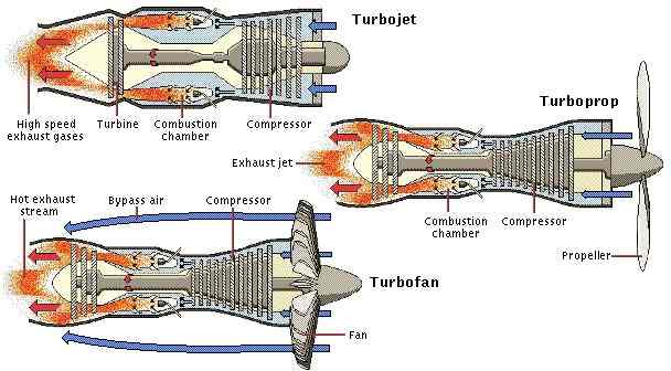
Turbojet, Turboprop and Turbofan jet engine configurations
The key to a practical jet engine was the gas turbine, used to extract energy to drive the compressor from the engine itself. The gas turbine was not an idea developed in the 1930s: the patent for a stationary turbine was granted to John Barber in England in 1791. The first gas turbine to successfully run self-sustaining was built in 1903 by Norwegian engineer Ægidius Elling. The first patents for jet propulsion were issued in 1917. Limitations in design and practical engineering and metallurgy prevented such engines reaching manufacture. The main problems were safety, reliability, weight and, especially, sustained operation.
On January 16, 1930, in England Frank Whittle submitted patents for his own design for a full-scale aircraft engine (granted in 1932). In 1935 Hans von Ohain started work on a similar design in Germany, seemingly unaware of Whittle's work.
Ohain approached Ernst Heinkel, one of the larger aircraft industrialists of the day, who immediately saw the promise of the design. Heinkel had recently purchased the Hirth engine company, and Ohain and his master machinist Max Hahn were set up there as a new division of the Hirth company. They had their first HeS 1 engine running by September 1937. Unlike Whittle's design, Ohain used hydrogen as fuel, which he credits for the early success. Their subsequent designs culminated in the gasoline-fuelled HeS 3 of 1,100 lbf (5 kN), which was fitted to Heinkel's simple and compact He 178 airframe and flown by Erich Warsitz in the early morning of August 27, 1939, from Marienehe aerodrome, an impressively short time for development. The He 178 was the world's first jetplane.
The engine was starting to look useful, and Whittle's Power Jets Ltd. started receiving Air Ministry money. In 1941 a flyable version of the engine called the W.1, capable of 1000 lbf (4 kN) of thrust, was fitted to the Gloster E28/39 airframe, and first flew on May 15, 1941 at RAF Cranwell.
One problem with both of these early designs, which are called centrifugal-flow engines, was that the compressor worked by "throwing" (accelerating) air outward from the central intake to the outer periphery of the engine, where the air was then compressed by a divergent duct setup, converting its velocity into pressure. An advantage of this design was that it was already well understood, having been implemented in centrifugal superchargers. However, given the early technological limitations on the shaft speed of the engine, the compressor needed to have a very large diameter to produce the power required. A further disadvantage was that the air flow had to be "bent" to flow rearwards through the combustion section and to the turbine and tailpipe.
Austrian Anselm Franz of Junkers' engine division (Junkers Motoren or Jumo) addressed these problems with the introduction of the axial-flow compressor. Essentially, this is a turbine in reverse. Air coming in the front of the engine is blown towards the rear of the engine by a fan stage (convergent ducts), where it is crushed against a set of non-rotating blades called stators (divergent ducts). The process is nowhere near as powerful as the centrifugal compressor, so a number of these pairs of fans and stators are placed in series to get the needed compression. Even with all the added complexity, the resulting engine is much smaller in diameter. Jumo was assigned the next engine number, 4, and the result was the Jumo 004 engine. After many lesser technical difficulties were solved, mass production of this engine started in 1944 as a powerplant for the world's first jet-fighter aircraft, the Messerschmitt Me 262. Because Hitler wanted a new bomber the Me 262 came too late to decisively impact Germany's position in World War II, but it will be remembered as the first use of jet engines in service. After the end of the war the German Me 262 aircraft were extensively studied by the victorious allies and contributed to work on early Soviet and US jet fighters.
Centrifugal-flow engines have improved since their introduction. With improvements in bearing technology, the shaft speed of the engine was increased, greatly reducing the diameter of the centrifugal compressor. The short engine length remains an advantage of this design. Also, its engine components are robust; axial-flow compressors are more liable to foreign object damage.
British engines also were licensed widely in the US. Their most famous design, the Nene would also power the USSR's jet aircraft after a technology exchange. American designs would not come fully into their own until the 1960s.
Types
There are a large number of different types of jet engines, all of which get propulsion from a high speed exhaust jet.
Turbojet engines
A turbojet engine is a type of internal combustion engine often used to propel aircraft. Air is drawn into the rotating compressor via the intake and is compressed, through successive stages, to a higher pressure before entering the combustion chamber. Fuel is mixed with the compressed air and ignited by flame in the eddy of a flame holder. This combustion process significantly raises the temperature of the gas. Hot combustion products leaving the combustor expand through the turbine, where power is extracted to drive the compressor. Although this expansion process reduces both the gas temperature and pressure at exit from the turbine, both parameters are usually still well above ambient conditions. The gas stream exiting the turbine expands to ambient pressure via the propelling nozzle, producing a high velocity jet in the exhaust plume. If the jet velocity exceeds the aircraft flight velocity, there is a net forward thrust upon the airframe.
Under normal circumstances, the pumping action of the compressor prevents any backflow, thus facilitating the continuous-flow process of the engine. Indeed, the entire process is similar to a four-stroke cycle, but with induction, compression, ignition, expansion and exhaust taking place simultaneously, but in different sections of the engine. The efficiency of a jet engine is strongly dependent upon the overall pressure ratio (combustor entry pressure/intake delivery pressure) and the turbine inlet temperature of the cycle.
It is also perhaps instructive to compare turbojet engines with propeller engines. Turbojet engines take a relatively small mass of air and accelerate it by a large amount, whereas a propeller takes a large mass of air and accelerates it by a small amount. The high-speed exhaust of a jet engine makes it efficient at high speeds (especially supersonic speeds) and high altitudes. On slower aircraft and those required to fly short stages, a gas turbine-powered propeller engine, commonly known as a turboprop, is more common and much more efficient. Very small aircraft generally use conventional piston engines to drive a propeller but small turboprops are getting smaller as engineering technology improves.
The turbojet described above is a single-spool design, in which a single shaft connects the turbine to the compressor. Higher overall pressure ratio designs often have two concentric shafts, to improve compressor stability during engine throttle movements. The outer high pressure (HP) shaft connects the HP compressor to the HP turbine. This HP Spool, with the combustor, forms the core or gas generator of the engine. The inner shaft connects the low pressure (LP) compressor to the LP Turbine to create the LP Spool. Both spools are free to operate at their optimum shaft speed.
Turbofan engines
Most modern jet engines are actually turbofans, where the low pressure compressor acts as a fan, supplying supercharged air to not only the engine core, but to a bypass duct. The bypass airflow either passes to a separate 'cold nozzle' or mixes with low pressure turbine exhaust gases, before expanding through a 'mixed flow nozzle'.
Forty years ago there was little difference between civil and military jet engines, apart from the use of afterburning in some (supersonic) applications.
Civil turbofans today have a low specific thrust (net thrust divided by airflow) to keep jet noise to a minimum and to improve fuel efficiency. Consequently the bypass ratio (bypass flow divided by core flow) is relatively high (ratios from 4:1 up to 8:1 are common). Only a single fan stage is required, because a low specific thrust implies a low fan pressure ratio.
Today's military turbofans, however, have a relatively high specific thrust, to maximize the thrust for a given frontal area, jet noise being of little consequence. Multi-stage fans are normally required to achieve the relatively high fan pressure ratio needed for a high specific thrust. Although high turbine inlet temperatures are frequently employed, the bypass ratio tends to be low (usually significantly less than 2.0).
An approximate equation for calculating the net thrust of a jet engine, be it a turbojet or a mixed turbofan, is:
where:
While
the
Components
The components of a jet engine are standard across the different types of engines, although not all engine types have all components. The parts include:
Design considerations
The various components named above have constraints on how they are put together to generate the most efficiency or performance. However the performance and efficiency of an engine can never be taken in isolation; for example fuel/distance efficiency of a supersonic jet engine maximises at about mach 2, whereas the drag for the vehicle carrying it is increasing as a square law and has much extra drag in the transonic region. The highest fuel efficiency for the overall vehicle is thus typically at Mach ~0.85.
For the engine optimisation for its intended use, important here is air intake design, overall size, number of compressor stages (sets of blades), fuel type, number of exhaust stages, metallurgy of components, amount of bypass air used, where the bypass air is introduced, and many other factors. For instance, let us consider design of the air intake.
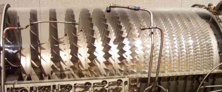
Jet aircraft engine compressor stage GE J79
Air intakes
Subsonic inlets
Pitot intakes are the dominant type for subsonic applications. A subsonic pitot inlet is little more than a tube with an aerodynamic fairing around it.
At zero airspeed (i.e., rest), air approaches the intake from a multitude of directions: from directly ahead, radially, or even from behind the plane of the intake lip.
At low airspeeds, the streamtube approaching the lip is larger in cross-section than the lip flow area, whereas at the intake design flight Mach number the two flow areas are equal. At high flight speeds the streamtube is smaller, with excess air spilling over the lip.
Beginning around 0.85 Mach, shock waves can occur as the air accelerates through the intake throat.
Careful radiusing of the lip region is required to optimize intake pressure recovery (and distortion) throughout the flight envelope.
Supersonic inlets
Supersonic intakes exploit shock waves to decelerate the airflow to a subsonic condition at compressor entry.
There are basically two forms of shock waves:
1) Normal shock waves, which are perpendicular to the direction of the flow. 2) Conical, or oblique, shock waves, which are angled rearwards, like the bow wave on a ship or boat. Note: Comments made regarding 3 dimensional conical shock waves, generally apply to 2D oblique shock waves
Normal shock waves tend to cause a larger drop in stagnation pressure, than the weaker conical shock waves. Basically, the higher the supersonic entry Mach number to a normal shock wave, the lower the subsonic exit Mach number and the stronger the shock. Although conical shock waves also reduce Mach number, the outlet flow remains supersonic.
A sharp-lipped version of the pitot intake described above for subsonic applications performs quite well at moderate supersonic flight speeds. A detached normal shock wave forms just ahead of the intake lip and 'shocks' the flow down to a subsonic velocity. However, as flight speed increases, the shock wave becomes stronger, causing a larger percentage decrease in stagnation pressure (i.e. poorer pressure recovery). An early US supersonic fighter, the F-100 Super Sabre, used such an intake.
More advanced supersonic intakes exploit a combination of conical shock wave/s and a normal shock wave to improve pressure recovery at high supersonic flight speeds. Conical shock wave/s are used to reduce the supersonic Mach number at entry to the normal shock wave, thereby reducing the resultant shock losses. An example of this was found on the SR-71's Pratt & Whitney J58s that could move a conical spike fore and aft within the engine nacelle, preventing the shockwave formed on the spike from entering the engine and stalling the engine, whilst keeping it close enough to give good compression.
Many second generation supersonic fighter aircraft featured an inlet cone, which was used to form the conical shock wave. This type of inlet cone is clearly seen on the English Electric Lightning and MiG-21 aircraft, for example. The same approach can be used for air intakes mounted at the side of the fuselage, where a half cone serves the same purpose with a semicircular air intake, as seen on the F-104 Starfighter and BAC TSR-2.
A more sophisticated approach is to angle the intake so that one of its edges forms a ramp. An oblique shockwave will form at start of this ramp. The Century series of US jets featured a number of variations on this approach, usually with the ramp at the outer vertical edge of the intake which was then angled back inwards towards the fuselage. Typical examples include the Republic F-105 Thunderchief and F-4 Phantom.
Later this evolved so that the ramp was at the top horizontal edge rather than the outer vertical edge, with a pronounced angle downwards and rearwards. This approach simplified the construction of the intakes and permitted the use of variable ramps to control the airflow into the engine. Most designs since the early 1960s now feature this style of intake, for example the F-14 Tomcat, Panavia Tornado and Concorde.
One of the problems with supersonic intakes is that they can deliver more corrected (or non-dimensional) flow than the engine itself can handle, particularly if the engine is throttled back. Some of the difference can be absorbed by the normal shock wave moving forward to a smaller flow area/lower entry Mach number, which weakens the shock, thereby reducing the outlet corrected flow. However, steps must be taken to prevent the normal shock from going forward of the intake lip, as this will disrupt the flow entering the intake. More extreme excesses in corrected flow can be accommodated by spilling air overboard through a trapdoor or supplementing the secondary flow of an ejector type final nozzle.
Compressors
Axial compressors rely on spinning blades that have aerofoil sections, similar to aeroplane wings. As with aeroplane wings in some conditions the blades can stall. If this happens, the airflow around the stalled compressor can reverse direction violently. Each design of a compressor has an associated operating map of airflow versus rotational speed for characteristics peculiar to that type (see compressor map). Many compressors are fitted with anti-stall systems in the form of bleed bands or variable geometry stators to decrease the likelihood of surge. Another method is to split the compressor into two or more units, operating on separate concentric shafts.
At a given throttle condition, the compressor operates somewhere along the steady state running line. Unfortunately, this operating line is displaced during transients. To help deal with this kind of issue many compressors are fitted with anti-stall systems in the form of bleed bands or variable geometry stators to decrease the likelihood of surge. Another ploy is to split the compressor into two or more units, operating on separate concentric shafts.
Another design consideration is the average stage loading. This can be kept at a sensible level either by increasing the number of compression stages (more weight/cost) or the mean blade speed (more blade/disc stress).
Although large flow compressors are usually all-axial, the rear stages on smaller units are too small to be robust. Consequently, these stages are often replaced by a single centrifugal unit. Very small flow compressors often employ two centrifugal compressors, connected in series. Although in isolation centrifugal compressors are capable of running at quite high pressure ratios (e.g. 10:1), impeller stress considerations (i.e. T3, NH implications) limit the pressure ratio that can be employed in high overall pressure ratio engine cycles.
Increasing overall pressure ratio implies raising the high pressure compressor exit temperature (i.e. T3). This implies a higher high pressure shaft speed, to maintain the datum blade tip Mach number on the rear compressor stage. Stress considerations, however, may limit the shaft speed increase, causing the original compressor to throttle-back aerodynamically to a lower pressure ratio than datum.
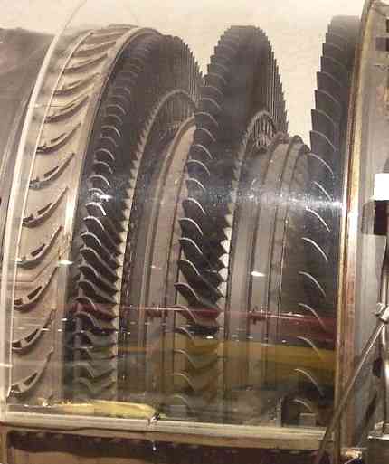
Jet aircraft engine turbine Stage GE J79
Combustors
Care must be taken to keep the flame burning in a moderately fast moving airstream, at all throttle conditions, as efficiently as possible. Since the turbine cannot withstand stoichiometric temperatures, resulting from the optimum combustion process, some of the compressor air is used to quench the exit temperature of the combustor to an acceptable level. Air used for combustion is considered to be primary airflow, while excess air used for cooling is called secondary airflow. Combustor configurations include can, annular, and can-annular.
Turbines
Because a turbine expands from high to low pressure, there is no such thing as turbine surge or stall. The turbine needs fewer stages than the compressor, because the mass of the fuel is added to the stream, the blades have more curvature and the gas streams faster.
Designers must, however, prevent the turbine blades and vanes from melting in a very high temperature and stress environment. Consequently bleed air extracted from the compression system is often used to cool the turbine blades/vanes internally. Other solutions are improved materials and/or special insulating coatings. The discs must be specially shaped to withstand the huge stresses imposed by the rotating blades. They take the form of impulse, reaction, or combination impulse-reaction shapes. Improved materials help to keep disc weight down.
Turbopumps
Turbopumps are used to raise the fuel pressure above the pressure in the combustion chamber so that it can be injected. Turbopumps are very commonly used with rockets, but ramjets also have been known to use them. The turbopump is usually driven by a gas turbine.
Nozzles
Nozzles turn the high temperature gas produced by the combustion process into a jet with a high velocity relative to the vehicle. The speed of the exhaust is crucial to the efficiency of a jet engine installed in an aircraft. Ideally, the jet exhaust would stop relative to the ground or ambient air when leaving the engine, giving all of its energy to the vehicle. Due to momentum considerations, however, in practice some rearward movement is required to overcome atmospheric drag of the vehicle. The optimum speed of the exhaust depends on the speed of the vehicle, subsonic aircraft only require subsonic exhaust; supersonic vehicles require supersonic exhaust, and rockets require hypersonic exhaust. Another task for the nozzle is to keep the exhaust as close as possible to the ambient pressure; A difference in pressure between the exhaust and the free-stream causes drag.
Jet engines which do not require high performance use a simple convergent nozzle, which is relatively easy to design. However, the highest speed the exhaust gasses can attain with this type of flow is Mach 1. In order to create higher thrust, a convergent-divergent nozzle is used to surpass Mach 1. High-performance, afterburning engines require a variable area nozzle for favorable performance across its entire range of speeds (take-off and landing, cruise, full throttle) in order to change the amount and speed of the thrust. Two types of variable nozzles have been utilized to date.
The simpler of the two is the ejector nozzle, which creates an effective nozzle through a secondary airflow and spring-loaded petals. At subsonic speeds, the airflow constricts the exhaust to a convergent shape. As the aircraft speeds up, the two nozzles dilate, which allows the exhaust to form a convergent-divergent shape, speeding the exhaust gasses past Mach 1. More complex engines can actually use a tertiary airflow to reduce exit area at very low speeds. Advantages of the ejector nozzle are relative simplicity and reliability. Disadvantages are average performance (compared to the other nozzle type) and relatively high drag due to the secondary airflow. Notable aircraft to have utilized this type of nozzle include the SR-71, Concorde, F-111, and Saab Viggen
For higher performance, it is necessary to use an iris nozzle. This type uses overlapping "petals" which mechanically adjusts the petals with hydraulics. Although more complex than the ejector nozzle, it has significantly higher performance and smoother airflow. As such, it is employed primarily on high-performance fighters such as the F-14, F-15, F-16, though is also used in high-speed bombers such as the B-1B.
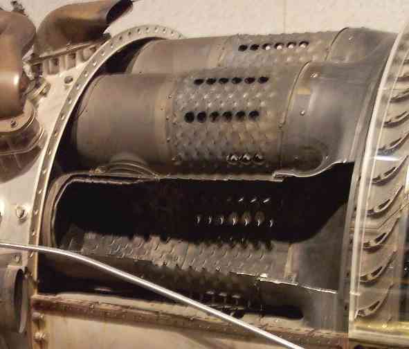
Jet aircraft engine combustion chamber GE J79
Rocket motors also employ convergent-divergent nozzles, but these are usually of fixed geometry, to minimize weight. Because of the much higher nozzle pressure ratios experienced, rocket motor con-di nozzles have a much greater area ratio (exit/throat) than those fitted to jet engines.
At the other extreme, some high bypass ratio civil turbofans use an extremely low area ratio (less than 1.01 area ratio), convergent-divergent, nozzle on the bypass (or mixed exhaust) stream, to control the fan working line. The nozzle acts as if it has variable geometry. At low flight speeds the nozzle is unchoked (less than a Mach number of unity), so the exhaust gas speeds up as it approaches the throat and then slows down slightly as it reaches the divergent section. Consequently, the nozzle exit area controls the fan match and, being larger than the throat, pulls the fan working line slightly away from surge. At higher flight speeds, the ram rise in the intake increases nozzle pressure ratio to the point where the throat becomes choked (M=1.0). Under these circumstances, the throat area dictates the fan match and being smaller than the exit pushes the fan working line slightly towards surge. This is not a problem, since fan surge margin is much better at high flight speeds. Cooling systems
All jet engines require high temperature gas for good efficiency, typically achieved by combusting hydrocarbon or hydrogen fuel. Combustion temperatures can be as high as 3500K (5000F), above the melting point of most materials.
Cooling systems are employed to keep the temperature of the solid parts below the failure temperature.
Air Systems
A complex air system is built into most turbine based jet engines, primarily to cool the turbine blades, vanes and discs.
Air, bled from the compressor exit, passes around combustor and is injected into the rim of the rotating turbine disc. The cooling air then passes through complex passages within the turbine blades. After removing heat from the blade material, the air (now fairly hot) is vented, via cooling holes, into the main gas stream. Cooling air for the turbine vanes undergoes a similar process.
Cooling the leading edge of the blade can be difficult, because the pressure of the cooling air just inside the cooling hole may not be much different from that of the oncoming gas stream. One solution is to incorporate a cover plate on the disc. This acts as a centrifugal compressor to pressurize the cooling air before it enters the blade. Another solution is to use an ultra-efficient turbine rim seal to pressurize the area where the cooling air passes across to the rotating disc.
A series of (e.g. labyrinth) seals allow a small flow of bleed air to wash the turbine disc to extract heat and, at the same time, pressurize the turbine rim seal, to prevent hot gases entering the inner part of the engine.
Small quantities of compressor bleed air are also used to cool the shaft, turbine shrouds, etc.
Rocket enginesRocket engines often use liquid coolant, typically the propellant is passed around the hot parts of the engine (regenerative cooling); but other techniques such as radiative cooling or dump cooling can be used.
Advanced designs
J-58 combined ramjet/turbojet
The SR-71's Pratt & Whitney J58 engines were rather unusual. They could convert in flight from being largely a turbojet to being largely a compressor-assisted ramjet. At high speeds (above Mach 2.4), the engine used variable geometry vanes to direct excess air through 6 bypass pipes from downstream of the fourth compressor stage into the afterburner. 80% of the SR-71's thrust at high speed was generated in this way, giving much higher thrust, improving specific impulse by 10-15%, and permitting continuous operation at Mach 3.2. The name coined for this configuration is turbo-ramjet.
Jet engine afterburner GE J79
Pre-cooled turbojet
Engines that may need to operate at near-hypersonic speeds could theoretically have much higher performance if a heat exchanger is used to cool the incoming air. The low temperature allows lighter materials to be used and combustors run at their maximum speeds (ordinarily, fuel flow must be reduced to prevent the turbines from melting, but doing so greatly reduces thrust)
This leads to plausible designs like SABRE, that might permit single-stage-to-orbit, and ATREX, that might permit jet engines to be used as boosters for space vehicles.
Nuclear-powered ramjet
Project Pluto was a nuclear-powered ramjet, intended for use in a cruise missile. Rather than combusting fuel as in regular jet engines, air was heated using a high-temperature, unshielded nuclear reactor. This raised the specific impulse of the engine by stupendous amounts, and the ramjet was predicted to be able to fly for months at supersonic speeds (Mach 3 at tree-top height). However, there was no obvious way to stop it once it had taken off, which is a great disadvantage. Unfortunately, because the reactor was unshielded, it was dangerous to be in or around the flight path of the vehicle (although the exhaust itself wasn't radioactive).
Scramjets
Scramjets are an evolution of the ramjet that are able to operate at much higher speeds than ramjets (or any other kind of airbreathing engine) are capable of reaching. They share a similar structure with ramjets, being a specially-shaped tube that compresses air with no moving parts through ram-air compression. Scramjets, however, operate with supersonic airflow through the entire engine. Thus, scramjets do not have the diffuser required by ramjets to slow the incoming airflow to subsonic speeds.
Scramjets start working at speeds of at least Mach 4, and have a theoretical maximum speed of Mach 17. Due to aerodynamic heating at these high speeds, scramjets are expected to be very heavy. Cooling, as a result, poses a challenge to engineers.
Trivia
ReferencesExternal links
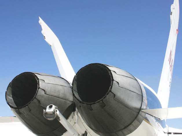
F-18 fighter plane afterburner nozzles
LINKS
AVIATION A - Z
A taste for adventure capitalists
Solar Cola - a healthier alternative
|
||||||||||||||||||||||||||||||||||||||||||||||||||||||||||||
|
This
website
is Copyright © 1999 & 2006 NJK. The bird |
||||||||||||||||||||||||||||||||||||||||||||||||||||||||||||
|
AUTOMOTIVE | BLUEBIRD | ELECTRIC CARS | ELECTRIC CYCLES | SOLAR CARS |