|
|
|||||||||||||||||||||||||||||||
|
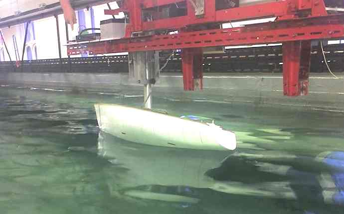
Even though we continue to refine our computer models and improve our understanding of fluid dynamics, fluid flow is still an extremely complicated, nonlinear phenomenon. Sometimes fast computers that can crunch tons of data are still no match for a design tool developed over 100 years ago - the hydraulic tank. When a model of the boat, or a part of the boat, is put in a large tank, the forces it encounters can be carefully controlled and monitored. Nothing is a mathematical approximation. The closer the model is to actual size, the more effective the test.
A model being tested in the Towing Tank of Newcastle University
A ship model basin may be defined as one of two separate yet related entities, namely:
In the second meaning, the company or authority is an engineering firm that acts as a contractor to the relevant shipyards, and provides hydrodynamic model tests and numerical calculations to support the design and development of ships and offshore structures.
The hydrodynamic test facilities present at a model basin site include at least:
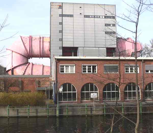
Cavitation tunnel of the Versuchsanstalt für Wasserbau und Schiffbau in Berlin
Some ship model basins have further facilities, for example:
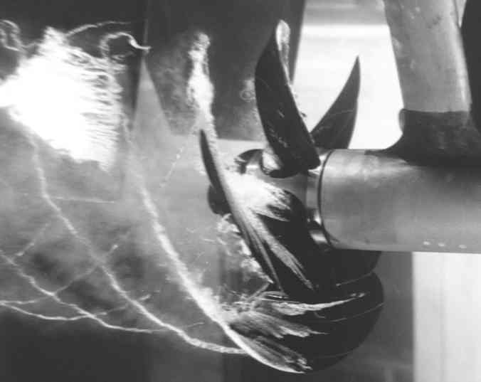
Cavitating propeller in a water tunnel experiment at the David Taylor Model Basin
Additionally, these companies or authorities have CFD software and experience to simulate the complicated flow around ships and their rudders and propellers numerically. Today's state of the art does not yet allow software to replace model tests in their entirety by CFD calculations. One reason, but not the only one, is that elementization is still expensive. Also the lines design of some of the ships is carried out by the specialists of the ship model basin, either from the beginning or by optimizing the initial design obtained from the shipyard. The same applies to the design of propellers.
The ship model basins worldwide are organized in the ITTC (International Towing Tank Conference) to standardize their model test procedures.
Some of the most significant ship model basins are the David Taylor Model Basin in the United States, SSPA [1] in Gothenburg, Sweden, the MARIN [2] in Wageningen, the Netherlands, the INSEAN in Rome, Italy, the HSVA[3] in Hamburg, Germany, the "Bassin d'essai des carènes" in Val de Reuil [4], France and CEHIPAR [5]in Madrid, Spain
HYDRODYNAMICS
Hydrodynamics (literally, "water motion") is fluid dynamics applied to liquids, such as water, alcohol, oil, and blood. However, this distinction from fluid dynamics as a whole is not always fully observed.
Blaise Pascal in the 1600s contributed some of the initial theory to this field. The term originates from the work of Daniel Bernoulli, based on the title of his work called Hydrodynamica (1738). He and Leonhard Euler established the general equations of hydrodynamics.
The practice was continued by Joseph Louis Lagrange (1736-1813) with the Euler-Lagrange system, Jean le Rond d'Alembert (1717-1783) discovered the Cauchy-Riemann equations, Pierre-Simon Laplace (1749-1827) with the governing equation in the potential flow named after him, Hermann Ludwig Ferdinand von Helmholtz (1821-1894) and William Thomson, Lord Kelvin (1824-1907) with Kelvin-Helmholtz instability (see also the Rayleigh-Taylor, Plateau-Rayleigh and Richtmyer-Meshkov instabilities) and Helmholtz's work on vortices.
FLUID DYNAMICS
Fluid dynamics is the sub-discipline of fluid mechanics dealing with fluids (liquids and gases) in motion. It has several subdisciplines itself, including aerodynamics (the study of gases in motion) and hydrodynamics (the study of liquids in motion). Fluid dynamics has a wide range of applications, including calculating forces and moments on aircraft, determining the mass flow rate of petroleum through pipelines, predicting weather patterns, understanding nebulae in interstellar space and reportedly modelling fission weapon detonation. Some of its principles are even used in traffic engineering, where traffic is treated as a continuous fluid.
Fluid dynamics offers a systematic structure that underlies these practical disciplines and that embraces empirical and semi-empirical laws, derived from flow measurement, used to solve practical problems. The solution of a fluid dynamics problem typically involves calculation of various properties of the fluid, such as velocity, pressure, density, and temperature, as functions of space and time.
Equations of fluid dynamics
The foundational axioms of fluid dynamics are the conservation laws, specifically, conservation of mass, conservation of momentum (also known as Newton's second law and third law), and conservation of energy. These are based on classical mechanics and are modified in quantum mechanics and general relativity. They are expressed using the Reynolds transport theorem.
In addition to the above, fluids are assumed to obey the continuum assumption. Fluids are composed of molecules that collide with one another and solid objects. However, the continuum assumption considers fluids to be continuous, rather than discrete. Consequently, properties such as density, pressure, temperature, and velocity are taken to be well-defined at infinitely small points, and are assumed to vary continuously from one point to another. The fact that the fluid is made up of discrete molecules is ignored.
For fluids which are sufficiently dense to be a continuum, do not contain ionized species, and have velocities small in relation to the speed of light, the momentum equations for Newtonian fluids are the Navier-Stokes equations, which are non-linear differential equations that describe the flow of a fluid whose stress depends linearly on velocity and on pressure. The un-simplified equations do not have a general closed-form solution, so they are only of use in computational fluid dynamics or when they can be simplified. The equations can be simplified in a number of ways, all of which make them easier to solve. Some of them allow appropriate fluid dynamics problems to be solved in closed form.
In addition to the mass, momentum and energy conservation equations, a thermodynamical equation of state giving the pressure as a function of other thermodynamic variables for the fluid is required to completely specify the problem. An example of this would be the perfect gas equation of state:
where p is pressure, ρ is density, Ru is the gas constant, M is the molecular mass and T is temperature.
Compressible vs incompressible flow
A fluid problem is called compressible if the pressure variation in the flowfield are large enough to effect substantial changes in the density of the fluid. Flows of liquids with pressure variations much smaller than those required to cause phase change (cavitation), or flows of gases involving speeds much lower than the isentropic sound speed are termed incompressible.
For flow of gases, to determine whether to use compressible or incompressible fluid dynamics, the Mach number of the problem is evaluated. As a rough guide, compressible effects can be ignored at Mach numbers below approximately 0.3. For liquids, whether the incompressible assumption is valid depends on the fluid properties (specifically the critical pressure and temperature of the fluid) and the flow conditions (how close to the critical pressure the actual flow pressure becomes). Acoustic problems require allowing compressibility, since sound waves can only be found from the fluid equations which include compressible effects.
The incompressible Navier-Stokes equations can be used to solve incompressible problems. They are simplifications of the Navier-Stokes equations in which the density has been assumed to be constant.
Viscous vs inviscid flow
Viscous problems are those in which fluid friction has significant effects on the solution.
The Reynolds number can be used to evaluate whether viscous or inviscid equations are appropriate to the problem.
Stokes flow is flow at very low Reynolds numbers, such that inertial forces can be neglected compared to viscous forces.
On the contrary, high Reynolds numbers indicate that the inertial forces are more significant than the viscous (friction) forces. Therefore, we may assume the flow to be an inviscid flow, an approximation in which we neglect viscosity at all, compared to inertial terms.
This idea can work fairly well when the Reynolds number is high, even if certain problems, such as those involving boundaries, may require that viscosity be included. Viscosity often cannot be neglected near boundaries because the no-slip condition can generate a region of large strain rate (a Boundary layer) which enhances the effect of even a small amount of viscosity, generating vorticity. Therefore, to calculate net forces on bodies (such as wings) we should use viscous equations. As illustrated by d'Alembert's paradox, a body in an inviscid fluid will experience no force. The standard equations of inviscid flow are the Euler equations. Another often used model, especially in computational fluid dynamics, is to use the Euler equations far from the body and the boundary layer equations, which incorporate viscosity, close to the body.
The Euler equations can be integrated along a streamline to get Bernoulli's equation. When the flow is everywhere irrotational and inviscid, Bernoulli's equation can be used throughout the field.
Steady vs unsteady flow
In the absence of turbulence, fluid flow can be described by streamlines. A streamline is a curve in the flowing fluid along which the fluid's velocity is constant in space. If, in addition, the particles making up the fluid flow along the streamlines, the flow is called steady. (See Landau & Lifshitz "Fluid Mechanics.") Steady flow is applicable to a large class of problems, such as lift and drag on a wing or flow through a pipe. Both the Navier-Stokes equations and the Euler equations become simpler when the steady flow approximation is valid. Problems where the flow is steady and for which all the streamlines have the same velocity over a cross-section of the flow, potential flow, are the most easily tractable.
The flow properties mentioned above, potential, steady, and unsteady, are not coordinate dependent and so cannot be transformed away by global coordinate transformations. For example Poisieulle flow, the flow of a viscous fluid in a tube, is not potential because the streamlines have different velocities and at the tube wall the velocity actually vanishes. It may be assumed steady in some cases but there is no coordinate system in which it is potential flow. Similarly, the flow in the vicinity of a surface is not steady because molecules in the flow that encounter the surface itself, i.e. in the boundary layer, are slowed by collisions with the surface and with molecules in the boundary layer.
If a problem is incompressible, irrotational, inviscid, and steady, it can be solved using Laplace's equation. Problems in this class have elegant solutions which are linear combinations of well-studied elementary flows.
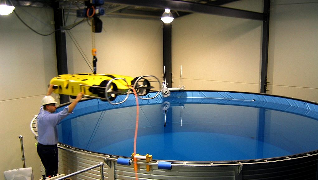
NEWCASTLE - This test tank provides the capability for comprehensive in-water testing of ROVs of all types. The tank includes viewing portholes to enable clear observation of underwater ROV behaviour. Diameter: 8m - Depth: 5m - Capacity: 250,000L.
Laminar vs turbulent flow
Turbulence is flow dominated by recirculation, eddies, and apparent randomness. Flow in which turbulence is not exhibited is called laminar. It should be noted, however, that the presence of eddies or recirculation does not necessarily indicate turbulent flow - these phenomena may be present in laminar flow as well. Mathematically, turbulent flow is often represented via Reynolds decomposition, in which the flow is broken down into the sum of a steady component and a perturbation component.
It is believed that turbulent flows obey the Navier-Stokes equations. Direct numerical simulation (DNS), based on the incompressible Navier-Stokes equations, makes it possible to simulate turbulent flows with moderate Reynolds numbers (restrictions depend on the power of computer and efficiency of solution algorithm). The results of DNS agree with the experimental data.
Most flows of interest have Reynolds numbers too high for DNS to be a viable option (source: Pope, 2000), given the state of computational power for the next few decades. Any flight vehicle large enough to carry a human (L > 3 m), moving faster than 72 km/h (20 m/s) is well beyond the limit of DNS simulation (Re = 4 million). Transport aircraft wings (such as on an Airbus A300 or Boeing 747) have Reynolds numbers of 40 million (based on the wing chord). In order to solve these real life flow problems, turbulence models will be a necessity for the foreseeable future. Reynolds-averaged Navier-Stokes equations combined with turbulence modeling provides a model of the effects of the turbulent flow, mainly the additional momentum transfer provided by the Reynolds stresses, although the turbulence also enhances the heat and mass transfer. Large eddy simulation also holds promise as a simulation methodology, especially in the guise of detached eddy simulation (DES), which is a combination of turbulence modeling and large eddy simulation.
Newtonian vs non-Newtonian fluids
Sir Isaac Newton showed how stress and the rate of change of strain are very close to linearly related for many familiar fluids, such as water and air. These Newtonian fluids are modeled by a coefficient called viscosity, which depends on the specific fluid.
However, some of the other materials, such as emulsions and slurries and some visco-elastic materials (eg. blood, some polymers), have more complicated non-Newtonian stress-strain behaviours. These materials include sticky liquids such as latex, honey, and lubricants which are studied in the sub-discipline of rheology.
Other approximations
There are a large number of other possible approximations to fluid dynamic problems.
Stokes flow is flow at very low Reynolds numbers, such that inertial forces can be neglected compared to viscous forces. Remark that solutions to this problem are reversible in time, i.e. still make sense reversing the motion. On the contrary, the inviscid flow is an approximation in which we neglect viscosity at all, compared to inertial terms. This idea, which leads to hyperbolic equations to solve, can work far from boundaries (walls, etc.) when the Reynolds number is high.
The Boussinesq approximation neglects variations in density except to calculate buoyancy forces and is appropriate for free convection problems.
LINKS and REFERENCE
http://www.uvs.com.au/services/hydrostatic-pressure-testing Batchelor, G.K. (1967) "An Introduction to Fluid Dynamics" (Cambridge University Press). Shinbrot, Marvin (1973) "Lectures on Fluid Mechanics" (Gordon and Breach). Landau, L.D. and Lifshitz, E.M. (1987) "Fluid Mechanics" (Pergamon Press). Acheson, D.J. (1990) "Elementary Fluid Dynamics" (Clarendon Press). Fluid Mechanics @ Chemical Engineering Information Exchange Geophysical and Astrophysical Fluid Dynamics SOLSI - An example of Enterprise realising Fluid Dynamics studies Ultramarine Inc. web page on vessel modeling
The latest Solarnavigator is a battery electric trimaran with an extremely stable active hull that runs on solar power. Stability is essential to effective energy harvesting. The model shown here is just 150mm long. The radio controlled test model is 2.1 meters in length, which may also become a test-bed for basic collision avoidance, as part of an autonomous development programme.
|
|||||||||||||||||||||||||||||||
|
This website is copyright © 1991- 2016 Electrick Publications. All rights reserved. The bird logo and names Solar Navigator and Blueplanet Ecostar are trademarks ™. The Blueplanet vehicle configuration is registered ®. All other trademarks hereby acknowledged and please note that this project should not be confused with the Australian: 'World Solar Challenge'™which is a superb road vehicle endurance race from Darwin to Adelaide. Max Energy Limited is an educational charity.
|