|
SUN TRACKER'S ELECTRONICS
|
||||||||||||||||||||||||||||||
|
INDEPENDENT WING CONTROL
Having
solar panels give you virtually free energy is great but the only draw
back is that it’s got to be sunny and the solar panels must point
towards the sun. But hang on a moment, our ship is not always going to be
aligned with the sun. So, we need to make
the ship capable of aligning it's solar panels to the sun for optimum
collection, regardless of the direction the boat is going.
Photoresistor comparator test circuit that worked. Two Hitec servos simulated the load, in this case moving our solar wings to face the sun at 90 degrees.
How can this be done? We need some way of "seeing" where the sun is, then using that information to tell the panels where to point. Ideally, this must be achieved automatically to free the crew and ensure accuracy (this ship needs no crew). Fortunately, thanks to electronics there are many different ways in which to measure light, or sunlight - usually by a photo reactive sensor, or photocell. Provided we set up a suitable photocell such that it detects direction, we could then tell where the sun is. But only a few sensors are reliable and rugged enough to be put on a ship that is going to be exposed to a harsh marine environment.
So,
now that we can see where the sun is we need to be able to use this
information to move the solar panels. Obviously, we need a motor
drive to move the panels. For simplicity we are going to use a
radio control type digital proportional servo. But hang about,
doesn't that use lots of power and we don’t want to be wasting
power which we could be using to drive the boat. So we need to make sure we are going to
move the solar panels in the right direction first time. To be
sure we achieve this we will use dual sensors on each side of the ship, plus there will a
scanning sensor mounted on the bridge of the ship.
All
this data that we can get from the sensors is great but what do we do
with it all. Well, to start with we need to process the data first as the
signals will be coming in various forms i.e. Digital and analogue.
Once
this data is inside the control systems we can do some dare I say it;
mathematics. This is were it all start getting rather complicated.
RISK Processor
The
control system needs to be able process millions of signals every second
and determine what action it should take. To make things run even faster
we are going to implement mutli processor functions. Meaning that we
will have several computer control systems to process the signals.
For
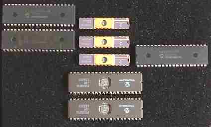
all this computing power we will be using PICs from Microchip.
These
are small yet highly powerful devices. PICs are available with
loads of onboard hardware functions such as USART PWM capture and so on.
I know it's all getting a bit technical, but sometimes you have to
knuckle down to get things done. If the terms are a bit
worrying, ignore the details for now - jus
It is estimated that the expedition will take 280 days, or 9 months. If we multiply 280 x 10 (potentially active) hours per day: 8am to 5pm = 2,800 hours x 6 (sampling every10 minutes to save energy) = 16,800 readings over the duration of the circumnavigation. There is no point sampling and comparing when the sun has gone down. After that all we need to keep an eye on is the weather - just in case the wings need to be folded for protection, or to prevent capsize risk from high winds.
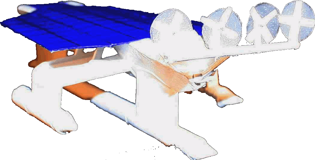
Despite the number of measurements, It is proposed that instructions to move the wing-panels are only given when a significant departure from the ideal 90 degrees to sunlight is detected. This is so as not to waste energy with multiple unnecessary wing movements. As you can see from the diagram of the robot ship below, tracking the sun has the effect of increasing the hours per day that energy can be usefully collected.
More information of the route, to include course headings are on the Global Expedition page.
Check out the experiment by Brooklyn Polytechnic University, Department of Aerospace and Mechanical Engineering. http://mechanical.poly.edu/
COMPONENTS:
Light
sensor: LDR Sensor
processor: microchip PIC comparator Maths
processor: microchip PIC Serial
port override: handheld device or laptop Actuator
drive: independently controlled by microchip PIC Actuator feedback sensor: processed by microchip PIC
SOLAR TRACKING THEORY & PRACTICAL EXAMPLES SOLAR WING PANEL ACTUATORS & CONTROL KITS ELECTRONIC COMPUTER CHIP SUN TRACKING SOLUTION MPPT ELECTRONIC SUN TRACKER PCB DEVELOPMENT
The ultimate Robot Boat. Solarnavigator uses an advanced SWASSH hull as the platform to mount the world's first autonomous circumnavigation. A successful expedition could pave the way for improved safety at sea.
|
||||||||||||||||||||||||||||||
|
This website is copyright © 1991- 2013 Electrick Publications. All rights reserved. The bird logo and names Solar Navigator and Blueplanet Ecostar are trademarks ™. The Blueplanet vehicle configuration is registered ®. All other trademarks hereby acknowledged and please note that this project should not be confused with the Australian: 'World Solar Challenge'™which is a superb road vehicle endurance race from Darwin to Adelaide. Max Energy Limited is an educational charity working hard to promote world peace.
|
||||||||||||||||||||||||||||||
|
AUTOMOTIVE | BLUEPLANET BE3 | ELECTRIC CARS | ELECTRIC CYCLES | SOLAR CARS | SOLARNAVIGATOR |

