|
PATENT
NUMBER: 7789723
Filing date: Jul 30, 2004
Issue date: Sep 7, 2010
Application number: 10/565,449
An
unmanned, autonomous, waterborne vehicle (500) for marine use capable of
operating on and below the surface of water, said vehicle (500) including
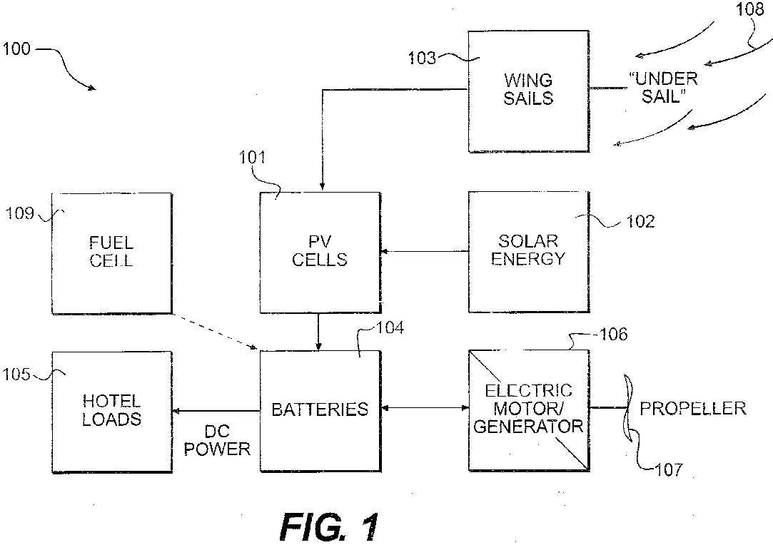
an enclosed hull (501) having a payload bay (506), a hybrid propulsion
system having energy collection means (504) in the form of a wing sail
(503) covered with photovoltaic cells and energy storage means (511) for
utilizing at least solar energy and wind energy, a plurality of sensors
(508, 514) for detecting predetermined environmental parameters and a
communications system (509, 515) for transmitting data from said sensors
(508, 515) to and for receiving command signals from one or more remote
stations and/or cooperating vehicles.
Inventors: Robert
A. Dane, Edward
Payne Kilbourn
Original Assignee: Solar
Sailor Pty Ltd
SOLAR SAILOR PTY LTD.
1 KATHERINE STREET
SUITE 206
CHATSWOOD, NEW SOUTH WALES, AUSTRALIA 2067
Primary Examiner: Ajay Vasudeva
Attorney: Thomas, Karceski, Raring & Teague, P.C.
Current U.S. Classification: 440/6;
114/39.21;
114/312;
114/333;
114/337
View
patent at USPTO
Search
USPTO Assignment Database
Robert
dane
CITATIONS
| US4102291 |
Sep 29, 1976 |
Jul 25, 1978 |
|
Electrical
generator for a sailboat |
| US4159427 |
Dec 20, 1976 |
Jun 26, 1979 |
Messerschmitt-Boelkow-Blohm
Gesellschaft mit beschraenkter Haftung |
Apparatus
for utilizing natural energies |
| US4371347 |
Apr 3, 1980 |
Feb 1, 1983 |
|
Wave
motor, especially for propulsion of boats |
| US5236378 |
Aug 4, 1992 |
Aug 17, 1993 |
|
Storage
of photovoltaic arrays on a ship |
| US5291847 |
Oct 14, 1992 |
Mar 8, 1994 |
|
Autonomous
propulsion within a volume of fluid |
| US5449307 |
Dec 6, 1993 |
Sep 12, 1995 |
|
Sea
surveillance and control apparatus |
| US5687137 |
Jan 10, 1996 |
Nov 11, 1997 |
Massachusetts Institute of
Technology |
Methods
and apparatus for adaptive oceanographic sampling |
| US5713293 |
Sep 22, 1995 |
Feb 3, 1998 |
The United States of America as
represented by the Secretary of the Navy |
Unmanned
sea surface vehicle having a personal watercraft hull form |
| US5863228 |
Apr 29, 1996 |
Jan 26, 1999 |
Solomon Technologies, Inc. |
Method
and apparatus for propelling a marine vessel |
| US5894450 |
Apr 15, 1997 |
Apr 13, 1999 |
Massachusetts Institute of
Technology |
Mobile
underwater arrays |
| US5995882 |
Feb 12, 1997 |
Nov 30, 1999 |
|
Modular
autonomous underwater vehicle system |
| US6273015 |
May 1, 2000 |
Aug 14, 2001 |
Maruta Electric Boatworks LLC |
Stabilized
electric watercraft for high speed cruising, diving and
sailing |
| US6536272 |
Aug 4, 2000 |
Mar 25, 2003 |
University of Miami
International Society of Ocean Monitoring and Research |
Water
monitoring, data collection, and transmission module |
| US6807921 |
Mar 7, 2002 |
Oct 26, 2004 |
|
Underwater
vehicles |
| US6854406 |
Apr 10, 2003 |
Feb 15, 2005 |
Board of Regents, The
University of Texas System |
Autonomous
surface watercraft |
| US7290496 |
Oct 12, 2006 |
Nov 6, 2007 |
|
Unmanned
autonomous submarine |
REFERENCED
BY
| US8123577 |
Jul 9,
2009 |
Feb 28,
2012 |
Argopower, LLC |
Autonomous
vehicle with fuel cell and autonomous flushing system |
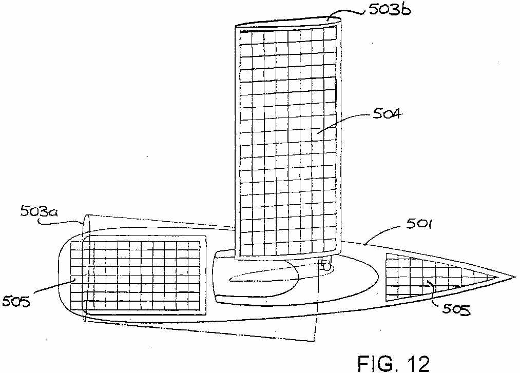
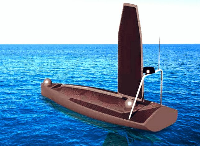
Wing-sail
system as seen in the patent
CLAIMS
1.
An unmanned ocean vehicle for operating either on or below the
surface of a body of water, said vehicle comprising:
an
enclosed hull having a payload bay; a
hybrid propulsion system having energy collectors and energy
stores utilising at least
-
(i) solar energy,
-
(ii) wave or water
current energy, and
-
(iii) wind energy;
-
a
plurality of sensors for detecting predetermined environmental
parameters; and
a
communications system for transmitting data from said sensors about
selected environmental parameters to, and for receiving command
signals from, one or more remote stations;
wherein
the hybrid propulsion system includes an electrical machine
mechanically coupled to a fluid drive element, and wherein the
electrical machine is supplied from the energy stores to drive the
fluid drive element in a motor mode, and wherein the vehicle further
includes ballast tanks for selective submerging and re-surfacing of
the vehicle to facilitate selective operation on or below the water
surface.
2.
The unmanned ocean vehicle of claim 1 wherein the hull has an outer
configuration having the general appearance of an aquatic animal.
3.
The unmanned ocean vehicle of claim 1 wherein the hybrid propulsion
system includes a wing sail having an aerofoil configuration for
propelling the vehicle using wind energy and having solar energy
collectors disposed on the surface of the wing sail.
4.
The unmanned ocean vehicle of claim 3 wherein the wing sail may be
lowered to a declined position along the hull of the vehicle to
reduce drag whilst continuing to collect solar energy.
5.
The unmanned ocean vehicle of claim 1 wherein the energy stores
includes electrical storage cells coupled to solar energy
collectors.
6.
The unmanned ocean vehicle of claim 1 wherein the energy stores
include rapid energy discharge devices to provide the vehicle with a
short sprint capability.
7.
The unmanned ocean vehicle of claim 6 wherein the rapid energy
discharge devices comprise electrical capacitors.
8.
The unmanned ocean vehicle of claim 6 wherein the rapid energy
discharge devices comprise fluid accumulators.
9.
The unmanned ocean vehicle of claim 1 wherein the payload bay is
internally powered in order to carry electronic equipment supporting
the environmental sensors for oceanographic or military use.
10.
The unmanned ocean vehicle of claim 1 wherein the environmental
sensors include sensors selected from the group including:
anemometers, wind vanes, radars, radio frequency interceptors,
optical band sensors, infrared band sensors, chemical/biological
sensors, ocean current sensors, acoustic sensors, and bathymetric
sensors.
11.
The unmanned ocean vehicle of claim 1 wherein the communications
system comprises a global positioning system (GPS) receiver, a LFB/SWB/marine
band transceiver, a wide band transceiver, and a satellite
transceiver, together with suitable antenna arrays.
12.
The unmanned ocean vehicle of claim 11 wherein the antenna arrays
include deployable antennae arrays, suited to towed operation when
receiving signals ranging from extremely low frequency (ELF) band to
super high frequency (SHF) band, capable of transmission and
reception in these bands.
13.
The unmanned ocean vehicle of claim 11 wherein the hybrid propulsion
system includes a wing sail having an aerofoil configuration for
propelling the vehicle using wind energy and having solar energy
collectors disposed on the surface of the wing sail and wherein the
antenna arrays are integrated into the wing sail or mounted on a
stern portion of the enclosed hull.
14.
The unmanned ocean vehicle of claim 1 wherein the vehicle is able to
dive under the surface for prolonged periods using stored energy to
avoid ships, storms or for stealth operations.
15.
The unmanned ocean vehicle of claim 1 wherein the hybrid propulsion
system further includes a fuel cell for emergency use.
16.
The unmanned ocean vehicle of claim 1 wherein the hybrid energy
propulsion system further utilises, in addition to wind energy, wave
or water current energy, and solar energy, only renewable energy
sources, including: temperature differential; and sea water
activated batteries or fuel cells.
17.
The unmanned ocean vehicle of claim 1 wherein the hybrid propulsion
system includes an electrical machine coupled to a fluid drive
element, wherein the electrical machine is driven by the drive
element when the vehicle is propelled by wind acting on the hull and
sails to charge the energy stores in a generator mode.
18.
The unmanned ocean vehicle of claim 1 wherein the payload bay
carries life-saving or fire-fighting equipment for search and rescue
operations.
19.
The unmanned ocean vehicle of claim 1 wherein the communications
system is configured for transmitting and receiving command signals
and data from one or more cooperating ocean vehicles.
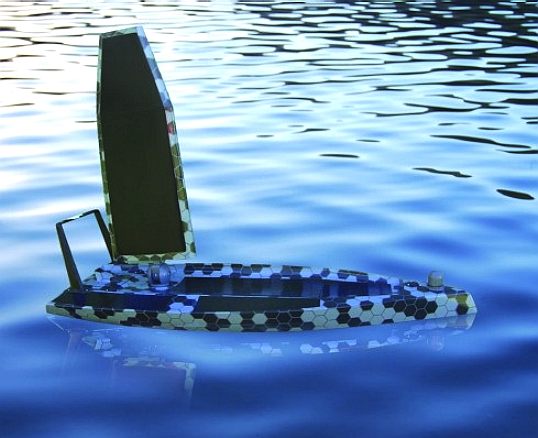
Man-O-War
model
PATENT
NUMBER: 8123577
Filing date: Jul 9, 2009
Issue date: Feb 28, 2012
Application number: 12/500,586
An
autonomous aquatic vehicle with one or more fuel cells, a controller, a
plurality of sensors, a battery, and at least one electric motor and
propeller. The one or more fuel cells provide power to the battery, and
the battery provides power for the vehicle. Seawater is provided to anodes
of the fuel cell and air or oxygen is provided to the cathode to produce
power for supply to the battery. The seawater-anode reaction creates waste
or byproduct that tends to decrease output of the fuel cell. The waste or
byproduct is automatically flushed from the fuel cell using seawater.
Inventor: Allan
Riggs
Original Assignee: Argopower,
LLC
Primary Examiner: Stephen Avila
Attorneys: Miles & Stockbridge P.C., David R. Schaffer,
Patrick L. Miller
Current U.S. Classification: 440/6
View
patent at USPTO
Search
USPTO Assignment Database
Download
USPTO Public PAIR data
CLAIMS
1. A buoyant autonomous aquatic vehicle comprising:
a base portion;
a controller to control autonomous operations of the aquatic vehicle, said controller being arranged on said base portion;
one or more sensors;
a power source to supply power for the aquatic vehicle;
a plurality of fuel cell devices to supply power to said power source for recharging, each said fuel cell device including a plurality of anode/cathode pairs;
a first partially submersible hull portion, said power source being housed by said first hull portion;
a second partially submersible hull portion, one of said fuel cell devices being housed by said second hull portion, and said second hull portion having a first plurality of apertures arranged on a bottom side thereof to allow entry of seawater to react with anodes of said one fuel cell device;
a third partially submersible hull portion, another of said fuel cell devices being housed by said third hull portion, and said third hull portion having a second plurality of apertures arranged on a bottom side thereof to allow entry of seawater to react with anodes of said another fuel cell device; and
first, second, and third electric motors respectively coupled to said first, second, and third hull portions to propel the aquatic vehicle,
wherein said second hull portion is configured to allow air from outside the second hull portion to access and interact with the cathodes of said one fuel cell device, and said second hull portion is configured substantially to prevent seawater passed through said first plurality of apertures from contacting the cathodes of said one fuel cell,
wherein said third hull portion is configured to allow air from outside the third hull portion to access and interact with the cathodes of said another fuel cell device, and said third hull portion is configured substantially to prevent seawater passed through said second plurality of apertures from contacting the cathodes of said another fuel cell, and
wherein said first and second plurality of apertures are configured to allow byproduct produced by reactions between the seawater and corresponding anodes to exit therethrough to outside the second hull portion and the third hull portion, respectively.
2. The buoyant autonomous aquatic vehicle according to claim 1, wherein the byproduct is substantially environmentally neutral.
3. The buoyant autonomous aquatic vehicle according to claim 1,
wherein the plurality of fuel cell devices are configured to facilitate extended-use anodes, the extended-use anodes initially being substantially longer than corresponding cathodes, and
wherein the extended-use anodes are physically biased by a biasing means for biasing the anodes.
4. The buoyant autonomous aquatic vehicle according to claim 1,
wherein said second electric motor is canted from the longitudinal axis of said second hull portion, and
wherein said third electric motor is canted from the longitudinal axis of said third hull portion.
5. The buoyant autonomous aquatic vehicle according to claim 4, wherein said second electric motor is canted at five degrees inward, toward said first hull portion, and said third electric motor is canted at five degrees inward, toward said first hull portion.
6. The buoyant autonomous aquatic vehicle according to claim 1, wherein the autonomous aquatic vehicle is configured to be controlled based on an off-vehicle controller.
7. The buoyant autonomous aquatic vehicle according to claim 1, wherein the autonomous aquatic vehicle is configured to be controlled based on a signal received from outside the vehicle.
8. The buoyant autonomous aquatic vehicle according to claim 1, wherein each said fuel cell device further is configured to supply power for the aquatic vehicle.
9. The buoyant autonomous aquatic vehicle according to claim 1, wherein each anode is fixedly attached to a support structure of the corresponding fuel cell device.
10. The buoyant autonomous aquatic vehicle according to claim 1, wherein each anode rests on a support structure of the corresponding fuel cell device.
11. The buoyant autonomous aquatic vehicle according to claim 1,
wherein said one fuel cell device includes a first support tray having a plurality of apertures formed by ribs to allow passage therethrough of the seawater having entered through the first plurality of apertures of the second hull portion, the first support tray being sealingly coupled to said second hull portion to create a water-tight seal therewith and to create a first void therebetween, and
wherein said another fuel cell device includes a second support tray having a plurality of apertures formed by ribs to allow passage therethrough of the seawater having entered through the second plurality of apertures of the third hull portion, the second support tray being sealingly coupled to said third hull portion to create a water-tight seal therewith and to create a second void
therebetween.
12. The buoyant autonomous aquatic vehicle according to claim 1,
wherein the second partially submersible hull portion houses a third one of said fuel cell devices, and
wherein the third partially submersible hull portion houses a fourth one of said fuel cell devices.
13. The buoyant autonomous aquatic vehicle according to claim 1,
wherein at least one aperture of the first plurality of apertures is configured to facilitate intake of seawater, and at least one aperture of the first plurality of apertures is configured to facilitate removal of the byproduct from the second hull portion therethrough, and
wherein at least one aperture of the second plurality of apertures is configured to facilitate intake of seawater, and at least one aperture of the second plurality of apertures is configured to facilitate removal of the byproduct from the third hull portion
therethrough.
14. The buoyant autonomous aquatic vehicle according to claim 13,
wherein the at least one aperture of the first plurality of apertures configured to facilitate intake of seawater is a scoop, and
wherein the at least one aperture of the second plurality of apertures configured to facilitate intake of seawater is a scoop.
15. The buoyant autonomous aquatic vehicle according to claim 1, wherein a filter extends over the opening of each of the apertures of the first and second plurality of apertures to prevent unwanted foreign objects from entering the second and third hull portions, respectively, and to allow the byproduct to exit the second and third hull portions, respectively.
16. The buoyant autonomous aquatic vehicle according to claim 1, wherein each individual fuel cell of said fuel cell devices is sealed to hold the seawater, but open at a top thereof to permit air to contact the cathode.
17. A method for operating a buoyant aquatic vehicle having a base, a controller to control operations of the vehicle, at least one sensor, a battery, first and second fuel cell apparatuses coupled to the battery, a first motor, and a second motor, a first hull that houses the first fuel cell apparatus, and a second hull that houses the second fuel cell apparatus, the method comprising:
providing seawater to anodes of the first fuel cell apparatus through a first plurality of openings in the first hull;
providing air to cathodes of the first fuel cell apparatus through a first air-permeable and water-proof opening of the first hull;
allowing discharge of a byproduct of the anodes of the first fuel cell through at least one of the openings of the first plurality of openings;
providing seawater to anodes of the second fuel cell apparatus through a second plurality of openings in the second hull;
providing air to cathodes of the second fuel cell apparatus through a second air-permeable and water-proof opening of the second hull;
allowing discharge of a byproduct of the anodes of the second fuel cell through at least one of the openings of the second plurality of openings; and
supplying to the battery, an output of at least one of the first fuel cell apparatus and the second fuel cell apparatus.
18. The method according to claim 17,
wherein the first fuel cell apparatus includes a first support tray to support a plurality of housing apparatuses housing respective anode/cathode pairs of the first fuel cell apparatus, the first support tray including a plurality of openings associated with each anode/cathode pair, each opening being formed by rib portions, and said providing seawater to anodes of the first fuel cell apparatus further comprises providing the seawater through the plurality of openings of the first support tray, and
wherein the second fuel cell apparatus includes a second support tray to support a plurality of housing apparatuses housing respective anode/cathode pairs of the second fuel cell apparatus, the second support tray including a plurality of openings associated with each anode/cathode pair, each opening being formed by rib portions, and said providing seawater to anodes of the second fuel cell apparatus further comprises providing the seawater through the plurality of openings of the second support tray.
19. The method according to claim 17, further comprising autonomously controlling the vehicle.
20. The method according to claim 17, wherein said supplying to the battery further comprises one of charging or recharging the battery.
21. The method according to claim 17, wherein said supplying to the battery further comprises maintaining an output level of the battery.
22. A floating aquatic vessel comprising:
means for floating the vessel;
means for moving the vessel;
means for controlling the vessel;
means for sensing a characteristic of the environment in which the vessel is situated;
means for supplying power to the vessel;
means for supplying fuel to said power supplying means;
means for providing salt water to said fueling means;
means for providing oxygen to said fueling means; and
means for removing a waste product created by said fueling means.
23. The vessel of claim 22, further comprising means for sensing a characteristic of the vessel.
24. The vessel of claim 22, wherein the waste is a slurry comprised of Magnesium.
25. The vessel of claim 22, wherein the waste is non-toxic to marine flora and fauna.
26. The vessel of claim 22, further comprising means for supporting one or more anodes of said means for fueling.
27. The vessel of claim 22, wherein said means for providing salt water to said fueling means includes a scoop.
28. The vessel of claim 22, wherein said means for providing salt water to said fueling means includes means for regulating unwanted objects with respect to said means for supplying fuel and for regulating exit of the waste product.
| US4885217 |
Jul
6, 1987 |
Dec
5, 1989 |
Alupower,
Inc. |
Air
cathodes and materials therefor |
| US4906535 |
Dec
20, 1988 |
Mar
6, 1990 |
Alupower,
Inc. |
Electrochemical
cathode and materials therefor |
| US4950561 |
Jun
29, 1989 |
Aug
21, 1990 |
Eltech
Systems Corporation |
Metal-air
battery with easily removable anodes |
| US4950562 |
Apr
19, 1989 |
Aug
21, 1990 |
Toa
Nenryo Kogyo Kabushiki Kaisha |
Solid
electrolyte type fuel cells |
| US5032473 |
Apr
27, 1990 |
Jul
16, 1991 |
Alupower,
Inc. |
Electrochemical
cathode |
| US5053375 |
Jan
8, 1990 |
Oct
1, 1991 |
Alupower,
Inc. |
Electrochemical
cathode and materials therefor |
| US5292598 |
Apr
21, 1993 |
Mar
8, 1994 |
|
Method
for renewing fuel cells using magnesium anodes |
| US6009823 |
Oct
27, 1998 |
Jan
4, 2000 |
|
Marine
scoop strainer with cleaning access |
| US6250235 |
Aug
1, 2000 |
Jun
26, 2001 |
Global
New Energy Technology Corporation |
Method
and product for improved fossil fuel combustion |
| US6706432 |
Aug
1, 2001 |
Mar
16, 2004 |
Magpower
Systems, Inc. |
Methods
and products for improving performance of batteries/fuel
cells |
| US6854406 |
Apr
10, 2003 |
Feb
15, 2005 |
Board
of Regents, The University of Texas System |
Autonomous
surface watercraft |
| US7789723 |
Jul
30, 2004 |
Sep
7, 2010 |
Solar
Sailor Pty Ltd |
Unmanned
ocean vehicle |
| US7938077 |
May
27, 1993 |
May
10, 2011 |
The
United States of America as represented by the Secretary
of the Navy |
Hydrogen
generation apparatus for an underwater vehicle |
| US20030054208 |
Aug
1, 2001 |
|
|
Method
and products for improving performance of batteries/fuel
cells |
| US20050016430 |
Aug
23, 2004 |
|
|
Autonomous
surface watercraft |
ECONOMICS
Rationale
Ii
is a common misconception that there
are four primary incentives embodied in the patent system:
1.
the incentive
to invent in the first place;
2.
the incentive to disclose the invention once
made;
3.
the incentive to invest the sums necessary to experiment, to
produce, and finally get the invention on the market;
4.
and the incentive to
design around and improve upon earlier patents.
1.
Unfortunately patents do not provide incentives for economically efficient research and
development (R&D) because of the high cost of the patent and the fact
that many inventions are from individuals of limited means and not
corporations with a large R&D budget. Many large modern corporations have annual R&D
budgets of hundreds of millions or even billions of dollars leaving them
to believe that they know all there is to know, and so are loath to enter
into agreements with individuals who may have acquired patent rights -
because they know that that know-how will soon be available to them free
of charge and without any cost attaching. History shows us that
individuals come up with most of the ground breaking ideas - not
corporations. Invention is as the result of a lateral spark, not grinding
research.
2.
Without
patents, R&D spending would be significantly less or eliminated
altogether, but this would not stop technological advances or
breakthroughs, because of the spark of lone inventors. The present patent
system thus works to persuade corporations to maintain R&D budgets,
and to give them a virtual monopoly on intellectual property and finance
for developing that intellectual property. This second justification does
not give inventors any real protection for their ideas, more, it tricks
them into believing that they might benefit from patent protection, when
in fact no such protection exists where a corporation can freely copy
their work secure in the knowledge that the lone inventor cannot afford to
litigate in the patent of trademark courts - and that if they were to try,
the establishment - especially the trademark courts would wipe them out
with costs awards left right and center, as clever corporate lawyers used
the system to win by attrition. This is the real world. It has been
designed by corporations for corporations and shareholders, with
politicians simply going along for the ride - in some case to protect
their investments in corporations.
The
notion of disclosing innovations into the public
domain for the common good, is counter productive to the aim of 'letters
patent' to protect the ideas of the inventor. As described above an
inventor does not have the legal protection
of patents, because they do not have the wherewithal to litigate. For this
reason it is better to keep their
inventions secret, until governments wake up to the facts. The facts are
that inventors need to eat and pay mortgages too. And that is why so many
inventors end up bankrupt. The system is grossly unfair when compared to
writers and artists who benefit free of charge from copyright.
3.
In many industries (especially those with high fixed costs and either low
marginal costs or low reverse engineering costs - computer processors,
software, and pharmaceuticals being prototypical examples), once an
invention exists, the cost of commercialization (testing, tooling up a
factory, developing a market, etc.) is far more than the initial
conception cost. (For example, the internal "rule of thumb" at
several computer companies in the 1980s was that post-R&D costs were
7-to-1). Unless there is some way to prevent copies from competing at the
marginal cost of production, companies will not make that productization
investment. What this means is that by the time a product may be developed
by a lone inventor, his or her patent will have expired. Again, what is
the point of a patent that has no chance of providing the owner of those
rights, any real prospect of benefiting from the invention. Here we come
back to the unfairness of the patent system, where an artist, writer or
film maker has no such limitations.
4.
Patent rights do not create an incentive for companies to develop workarounds to
patented inventions for all the reasons above. Products will be improved
not because of any temporary state granted right, but because in order to
sell their goods, companies must offer some incremental market advantage.
The small-time
inventor cannot use the exclusive right status to become a licensor,
because companies know they can outgun him or her financially. It is utter
nonsense to suggest otherwise and anyone who does so is not speaking from
real life experience.
Man-O-War
illustration: Reflection on nature
Criticism
The four
cited incentives is not achieved by the patent system. The patent system has countervailing costs, and those costs fall
more heavily in some contexts than others. There are many critics and
criticisms of patents and this has resulted in the formation of a large
number of groups who oppose patents in general, or specific types of
patents, and who lobby for their abolishment.
One
criticism is that a patent confers a "negative right" upon a
patent owner, permitting them to exclude competitors from using or
exploiting the invention, even if the competitor subsequently develops the
same invention independently. This may be subsequent to the date of
invention, or to the priority date, depending upon the relevant patent
law. This argument must be viewed in the context of corporations
effectively taking control of the patents that they should not have rights
to.
Another
criticism is that monopolies may create inefficiency. If the grant of a
patent is the grant of a monopoly, the patent system may stifle
competition and result in higher prices, lower quality, and shortages. In
this context, patents are not socially optimal but are considered to be
second best alternatives. The solution is to grant protection to small
inventors, to include state funded legal assistance, provided that the
inventor licenses his or her invention to all companies at a low rate - to
encourage competition.
Another
theoretical problem with patent rights was proposed by law professors
Michael Heller and Rebecca Sue Eisenberg in a 1998 Science article.
Building from Heller's theory of the tragedy of the anticommons, the
professors postulated that intellectual property rights may become so
widely fragmented that, effectively, no one can take advantage of them as
to do so would require an agreement between the owners of all of the
fragments.
Since
at least the early 1980s, patent offices around the world have accepted
that computer programs can lie within the realm of patentable subject
matter, although the regulations for when a computer program is a
patentable invention differ markedly between countries. It is argued that
the resulting software patents inhibit innovation in contrast to the
underlying purpose of patents.
In
response to perceived problems with the grant of patents, and the evolving
nature of technology and industry, there is on-going debate about, and
reform of, patent systems around the world. The TRIPs agreement, developed
by the WTO has led to the alignment of many patent systems with regard to
certain controversial issues, such as what can be protected by patents and
the issue of compulsory licences in cases of national need.

-
Applying
-
The decision making process
-
Find patents
-
Journal
-
Managing your patents
-
Other people's patents
-
Forms and fees

EUROPEAN
PATENT OFFICE
The
European Patent Organisation is an intergovernmental organisation that was
set up on 7 October 1977 on the basis of the European Patent Convention (EPC)
signed in Munich in 1973. It has two bodies, the European Patent Office
and the Administrative Council, which supervises the Office's activities.
The Organisation currently has 32 member states.
The
European Patent Office (EPO) provides a uniform application procedure for
individual inventors and companies seeking patent protection in up to 37
European countries. It is the executive arm of the European
Patent Organisation and is supervised by the Administrative
Council .
The
Administrative Council was set up under Article
4, paragraph 2(b), EPC. Detailed provisions relating to the Council
can be found in Articles
26 to 36 EPC.
Chairman
/ Deputy Chairman
Chairman
Roland GROSSENBACHER, Directeur, Institut Fédéral de la Propriété
Intellectuelle (CH)
mail : council_chairman@epo.org
Deputy
Chairman
Benoît BATTISTELLI, Directeur général, Institut National de la Propriété
Industrielle (FR)
How
to apply for a patent: a simple guide to the grant procedure
epoline
Search
decisions of the boards of appeal
New
decisions
Pending
decisions
Business
distribution scheme
Forms

UNITED
STATES PATENT OFFICE
For over 200 years, the basic role of the United States Patent and
Trademark Office (USPTO) has remained the same: to promote the progress of
science and the useful arts by securing for limited times to inventors the
exclusive right to their respective discoveries (Article 1, Section 8 of
the United States Constitution). Under this system of protection, American
industry has flourished. New products have been invented, new uses for old
ones discovered, and employment opportunities created for millions of
Americans. The strength and vitality of the U.S. economy depends directly
on effective mechanisms that protect new ideas and investments in
innovation and creativity. The continued demand for patents and trademarks
underscores the ingenuity of American inventors and entrepreneurs. The
USPTO is at the cutting edge of the Nation’s technological progress and
achievement.
The USPTO is a federal agency in the Department of Commerce. The USPTO
occupies five interconnected buildings in Alexandria, Virginia. The office
employs over 7,000 full time staff to support its major functions--- the
examination and issuance of patents and the examination and registration
of trademarks.
The USPTO has evolved into a unique government agency. Since
1991--under the Omnibus Budget Reconciliation Act (OBRA) of 1990--the
agency has been fully fee funded. The primary services the agency provides
include processing patent and trademark applications and disseminating
patent and trademark information.
Through the issuance of patents, the USPTO encourages technological
advancement by providing incentives to invent, invest in, and disclose new
technology worldwide. Through the registration of trademarks, the agency
assists businesses in protecting their investments, promoting goods and
services, and safeguarding consumers against confusion and deception in
the marketplace. By disseminating both patent and trademark information,
the USPTO promotes an understanding of intellectual property protection
and facilitates the development and sharing of new technologies worldwide.
USPTO programs are conducted under the following principal
statutory authorities:
-
15 U.S.C. 1051-1127 contains provisions of the Trademark Act of
1946 that govern the administration of the trademark registration
system of the Patent and trademark Office.
-
15 U.S.C. 1511 states that the Patent and Trademark Office is
under the jurisdiction and supervision of the Department of Commerce.
-
35 U.S.C. contains basic authorities for administration of
patent laws, derived from the Act of July 19, 1952, and subsequent
enactment. Revenues from fees are available, to the extent provided
for in appropriations acts, to the Commissioner to carry out the
activities of the Office. The Patent and Trademark Office is
authorized to charge international fees for activities undertaken
pursuant to the Patent Cooperation Treaty. Deployment of automated
search systems of the Office to the public is authorized.
-
44 U.S.C. 1337-1338 contains authority to print patents,
trademarks, and other matters relating to the business of the Office.
 Patents Patents
- What
can be patented
- Who
may apply for a patent?
Trademarks
Copyrights
Domain
names
Trade
secrets
International
IP
What
are patents, trademarks,
servicemarks,
and copyrights?

ABOUT
IP AUSTRALIA
Patents
- Charter Service Level Commitments
Charter
Home | Patents
| Trade
Marks | Designs
| Plant
Breeder's Rights | Reports
Examination:
-
We
are working towards issuing first reports on applications for standard
patents within 14 months of receiving the request for
examination.
-
We
will examine and issue a report on your innovation patent within one
month of receiving the request for examination.
-
We
will issue an international search report for your application for a
patent within nine weeks of receiving the search copy
of the international application unless the application is for more
than one invention.
-
We
will issue an international-type search report for your application
for a patent within four weeks of receiving the
request for the search, unless the search request covers more than one
invention, or we ask you to supply a written search statement.
-
We
will respond to correspondence relating to the examination of your
application within four weeks of receiving it.
-
We
will achieve 95% compliance with all our published Product
Quality Standards (opens in new window).
Hearings:
Registration:
-
We
will seal your patent within one month after the
opposition period has expired, provided no one has opposed the
application and any applicable fees have been paid.
-
We
will grant your innovation patent, provided you have paid the fee and
complied with the formalities, within one month of
the application being lodged.
For
our current compliance with these commitments, go to our Charter
Report.
More
Patents statistics are available at our IP
Statistics page.
ONLINE
SERVICES
Apply
for your patent online
What
is a patent?
Before
you apply
The
application process
Maintaining
your patent
International
applications
Fees
Examples
Search
databases
Forms
& publications

The
Role of the Japan Patent Office
The
aim of industrial property (IP) system (general term for patent, utility
model, design, and trademark systems) is to contribute to the nation’s
industrial development through adequate protection and effective
utilization of inventions and other forms of intellectual creations. To
help promote science and technology, the IP system is expected to play an
increasingly important role in Japan in the 21st century.
The
Japan Patent Office (JPO) consists of the General Affairs Department, the
Examination Department, the Appeals Department, and other sections and
departments. The main functions of these departments include; 1) granting
adequate rights for patents, etc., 2) drafting plans for IP policies, 3)
international exchange and cooperation, 4) review of the IP system, and 5)
dissemination of information on IP. These functions provide for the
positive advancement of industrial development.
1.
Granting Exclusive Rights for Patents, Etc.
When
the JPO receives an application from anywhere in the world, its examiners
from the appropriate technical department must first conduct a strict
examination of the filed documents from the viewpoint of technological and
legal standards in order to determine whether exclusive patent or other
rights can or cannot be granted.
If there is an objection to the result of this examination, the Appeals
Department is authorized to act as the court of first instance for a local
court in strict accordance with the Civil Procedure Code
2.
Drafting Plans for Industrial Property Policies
In
order to realize a “Nation Built on Intellectual Property” for the
future, IP policies must be drafted and implemented to promote; 1) prompt
examination of patents, 2) support in the use of IP by regions as well as
small and mid-sized enterprises, 3) establishment of a “Japan brand”,
4) anti-counterfeit programs, and 5) create an environment which
encourages the “Intellectual Creation Cycle” (the cycle of creation,
protection, and exploitation).
3.
International Exchange and Cooperation
To
establish an IP environment aimed at an international harmonization, the
JPO has been actively working on international activities. Specifically,
it has been making collaborative efforts with the USPTO and EPO, extending
assistance to developing nations in such areas as office computerization,
examination processes, and human resources development, and implementing
tougher anti-counterfeiting measures.
4.
Review of the Industrial Property System
The
JPO continues to review and revise related laws and examination standards
based on plans drafted for IP policies, and on the results of
international negotiations.
5.
Dissemination of Information on Industrial Property
To
satisfy diversified user needs, the JPO has been expanding IP information
services. For example, improvements have been added to the Industrial
Property Digital Library (IPDL) services to be provided over the Internet.
We also started publishing DVD-ROM version official gazettes.
"You
have enemies? Good. That means you’ve stood up for something, sometime
in your life."
Sir
Winston Leonard Spencer Churchill (1874-1965)
The
Solar Navigator MkVI - SWASSH (Small Waterplane Area Stabilized Single
Hull) concept.
The
latest Solarnavigator is designed to be capable of an autonomous
world navigation set for an attempt
in
2015 if all goes according to schedule.
|