|
AUTONOMOUS
INDEPENDENT WING CONTROL - SINGLE AXIS TRACKING
Having
solar panels on the SolarNavigator autonomous ship gives us virtually free
energy to sail non-stop without the need to
dock for fuel. The draw
back of solar panels as an energy source is that it has got to be sunny and the solar panels must point
towards the sun to collect the maximum amount
of energy. This is often overlooked by boat
designers because the mechanical challenge seems insurmountable.
If
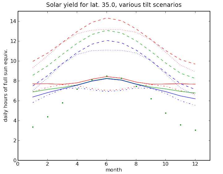
we were a 'summer only' boondocker, leaving our solar panels flat on the
deck makes good sense; no complicated wings. But, as our expedition will
be about nine months long tilting our solar panels can make a big
difference to total energy collected. Why? Because solar panels are most efficient when the sun
strikes them at a 90 degree angle.
But
the percentage increase, in terms of yield from a given panel area can
be significant, and is well worth looking at. These simple facts need to
be examined, since our ship is not always going to be
aligned with the sun during the voyage, simply because the sun rises in
the east and sets in the west
and the sun's relative position in the sky is lower in winter.
Thus, the angle that the sun's rays hit the solar panels (angle of
incidence) will vary at different times of the day and of course the
ship's position changes as it travels from waypoint to waypoint as you
can see from the route map.
Ideally
then, the ship needs to be capable of tilting its solar panels towards the sun for optimum
collection, regardless of the direction the boat is going.
Many solar powered boats don't have the ability to track the sun and it
is a difficult decision as to whether the additional manufacturing cost
and technical complications, make it worthwhile. Clearly,
it would be an advantage to be able to tilt the ships solar panels along
two axis, if we are to gain independence from the direction of travel
and still align the panels at 90 degrees to the sun at all times.
The
Turanor
PlanetSolar
had a rear panel that could change angle, but the other larger panels
did not have this ability. The PlanetSolar crew
were able to slide two large trays of panels (wings mounted on rails) in
and out of protective cover for storms, etc. But that ship could not
alter the angle of their side wing panels, such as to align with, or
track the sun. That means SolarNavigator will be pioneering this
technology afloat.
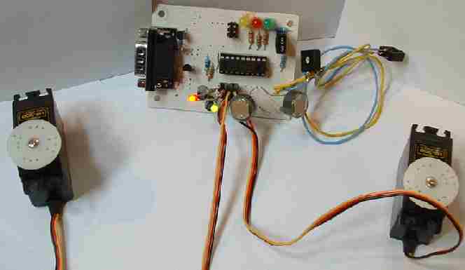
Photoresistor
comparator (early test rig circuit)
HOW
CAN THIS BE DONE?
We need some way of “seeing” where the sun is, then
using that information to tell the panels where to point. Ideally,
this should be achieved automatically to free the crew and ensure
accuracy. Fortunately, thanks to electronics there are many different ways in which
to measure light, or sunlight - usually by a photo reactive sensor, or
photocell. Provided we set up a suitable photocell such that it
detects direction, we could then tell where the sun is. But only a
few sensors are reliable and rugged enough to be put on a
ship that is going to be exposed to a harsh marine environment.
So,
now that we can see where the sun is we need to be able to use this
information to move the solar panels. Obviously, we need a motor
drive to move the panels. For simplicity we are going to use a
radio control type digital proportional servo. But hang about,
doesn't that use lots of power and we don’t want to be wasting
power which we could be using to drive the boat. So we need to make sure we are going to
move the solar panels in the right direction first time. To be
sure we achieve this we will use dual sensors on each side of the ship, plus there will a
scanning sensor mounted on the bridge of the ship.
All
this data that we can get from the sensors is great but what do we do
with it all. Well, to start with we need to process the data first as the
signals will be coming in various forms i.e. Digital and analogue.
Once
this data is in side the control systems we can do some dare I say it
mathematics. This is were it all start getting rather complicated.
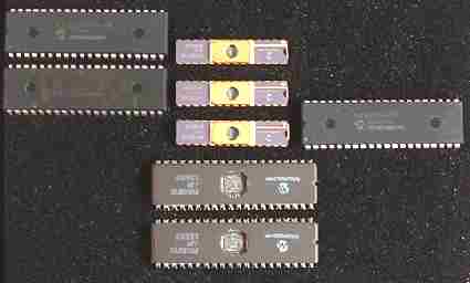
RISC
Processor
The
control system needs to be able process millions of signals every second
and determine what action it should take. To make things run even faster
we are going to implement multi processor functions. Meaning that we
will have several computers control systems to process the signals.
For
all this computing power we will be using PICs from Microchip.
These
are small yet highly powerful devices. PICs are available with
loads of onboard hardware functions such as USART PWM capture and so on.
I know it's all getting a bit technical, but sometimes you have to
knuckle down to get things done. If the terms are a bit
worrying, ignore the details for now - just hang in there for
the overview.
A
control system that can do all the calculations we want (work) is great, but sometimes your
going to get conditions that you just don’t expect. So it must have
some form of override. All the control systems are fitted with serial
ports and can talk to each other, like one fax machine to another. But should we need to take control
we can log into the system and remotely control the solar panels
manually.

COMPONENTS:
Light
sensor: LDR
Sensor
processor: microchip PIC comparator
Maths
processor: microchip PIC
Serial
port override: handheld device or laptop
Actuator
drive: independently controlled by microchip PIC
Actuator feedback sensor:
processed by microchip PIC
WHAT
IS A SOLAR TRACKER?
There
are two types of solar tracker. One is an electronic circuit that controls
charging current and voltage (MMPT) and the other is an electronic circuit
that controls the physical position of solar panels. In this article we
are concerned with the physical position of solar wing-panels - as in
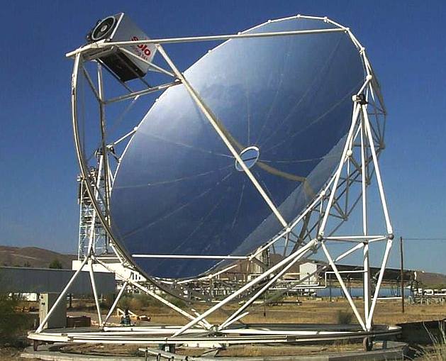
pointing the payload towards the sun. Payloads can be photovoltaic panels, reflectors, lenses or other optical devices.
In flat-panel photovoltaic (PV) applications, trackers are used to minimize the angle of incidence between the incoming light and a photovoltaic panel. This increases the amount of energy produced from a fixed amount of installed power generating capacity. In standard photovoltaic applications, it is estimated that trackers are used in at least 85% of commercial installations greater than 1MW from 2009 to 2012.
In concentrated photovoltaic (CPV) and concentrated solar thermal (CSP) applications trackers are used to enable the optical components in the CPV and CSP systems. The optics in concentrated solar applications accept the direct component of sunlight light and therefore must be oriented appropriately to collect energy. Tracking systems are found in all concentrator applications because such systems do not produce energy unless oriented closely toward the sun.
|
i
|
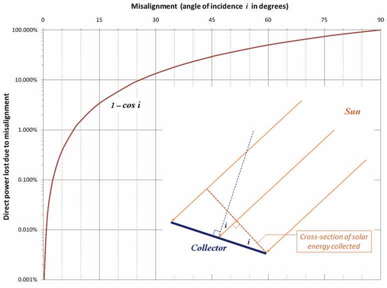
Lost
= 1 - cos(i)
|
|
i
|
hours
|
Lost
|
|
|
|
|
|
|
|
|
0°
|
0%
|
|
15°
|
1
|
3.4%
|
|
0.5°
|
0.007% |
|
22.5°
|
1.5
|
8.4%
|
|
1°
|
0.015%
|
|
30°
|
2
|
13.4%
|
|
3°
|
0.14%
|
|
45°
|
3
|
30%
|
|
5.5°
|
0.57%
|
|
53.5°
|
3.5
|
40%
|
|
8°
|
1%
|
|
60°
|
4
|
>50%
|
|
15°
|
4%
|
|
67.5°
|
4.5
|
>62%
|
|
23.4°
|
8.3%
|
|
75°
|
5
|
>75%
|
Direct power lost (%) due to misalignment (angle i )
BASIC CONCEPT
Sunlight has two components, the "direct beam" that carries about 90% of the solar energy, and the "diffuse sunlight" that carries the remainder - the diffuse portion is the blue sky on a clear day and increases as a proportion on cloudy days. As the majority of the energy is in the direct beam, maximizing collection requires the sun to be visible to the panels as long as possible.
The energy contributed by the direct beam drops off with the cosine of the angle between the incoming light and the panel. In addition, the reflectance (averaged across all polarizations) is approximately constant for angles of incidence up to around 50°, beyond which reflectance degrades rapidly.
For example trackers that have accuracies of ± 5° can deliver greater than 99.6% of the energy delivered by the direct beam plus 100% of the diffuse light. As a result, high accuracy tracking is not typically used in non-concentrating PV applications.
The sun travels through 360 degrees east-west a day, but from the perspective of any fixed location the visible portion is 180 degrees during an average 1/2 day period (more in spring and summer; less, fall and winter). Local horizon effects reduce this somewhat, making the effective motion about 150 degrees. A solar panel in a fixed orientation between the dawn and sunset extremes will see a motion of 75 degrees on either side, and thus, according to the table above, will lose 75% of the energy in the morning and evening. Rotating the panels to the east and west can help recapture these losses. A tracker rotating in the east-west direction is known as a single-axis tracker.
The sun also moves through 46 degrees north-south over the period of a year. The same set of panels set at the midpoint between the two local extremes will thus see the sun move 23 degrees on either side, causing losses of 8.3%.
A tracker that accounts for both the daily and seasonal motions is known as a dual-axis tracker. Generally speaking, the losses due to seasonal angle changes is complicated by changes in the length of the day, increasing collection in the summer in northern or southern latitudes. This biases collection toward the summer, so if the panels are tilted closer to the average summer angles, the total yearly losses are reduced compared to a system tilted at the spring/fall solstice angle (which is the same as the latitude).
There is considerable argument within the industry whether the small difference in yearly collection between single- and dual-axis trackers makes the added complexity of a two-axis tracker worthwhile. A recent review of actual production statistics from southern Ontario suggested the difference was about 4% in total, which was far less than the added costs of the dual-axis systems. This compares unfavourably with the 24-32% improvement between a fixed-array and single-axis tracker.
TYPES OF SOLAR COLLECTOR
Different types of solar collector and their location (latitude) require different types of tracking mechanism. Solar collectors may be:
non-concentrating flat-panels, usually photovoltaic or hot-water, concentrating systems, of a variety of types.
Solar collector mounting systems may be fixed (manually aligned) or tracking. Tracking systems may be configured as:
Fixed collector / moving mirror - i.e. Heliostat
Moving collector
Fixed mount
Domestic and small-scale commercial photovoltaic and hot-water panels are usually fixed, often flush-mounted on an appropriately facing pitched roof. Advantages of fixed mount systems (i.e. factors tending to indicate against trackers) include the following:
* Mechanical simplicity and hence lower installation and ongoing maintenance costs.
* Wind-loading: it is easier and cheaper to provision a sturdy mount; all mounts other than fixed flush-mounted panels must be carefully designed having regard to their wind loading due to their greater exposure.
* Indirect light: approximately 10% of the incident solar radiation is diffuse light, available at any angle of misalignment with the direct sun.
* Tolerance to misalignment: effective collection area for a flat-panel is relatively insensitive to quite high levels of misalignment with the sun – see table and diagram at Accuracy Requirements section below – for example even a 25° misalignment reduces the direct solar energy collected by less than 10%.
Fixed mounts are usually used in conjunction with non-concentrating systems, however an important class of non-tracking concentrating collectors, of particular value in the 3rd world, are portable solar cookers. These utilize relatively low levels of concentration, typically around 2 to 8 Suns and are manually aligned.
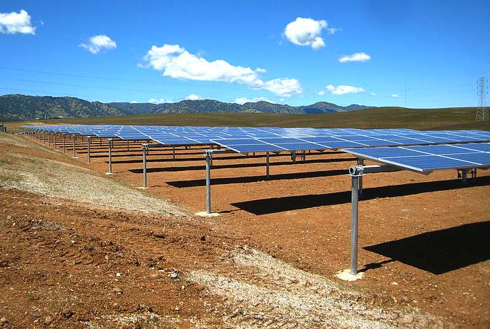
Floating ground mount
Solar trackers can be built using a “floating” foundation, which sits on top of the ground without the need for invasive concrete foundations. Instead of placing the tracker on concrete foundations, the tracker is placed on a gravel pan that can be filled with a variety of materials, such as sand or gravel, to secure the tracker to the ground. These “floating” trackers can sustain the same wind load as a traditional fixed mounted tracker. The use of floating trackers increases the number of potential sites for commercial solar projects since they can be placed on top of capped landfills or in areas where excavated foundations are not feasible.
Trackers
Even though a fixed flat-panel can be set to collect a high proportion of available noon-time energy, significant power is also available in the early mornings and late afternoons when the misalignment with a fixed panel becomes excessive to collect a reasonable proportion of the available energy. For example, even when the Sun is only 10° above the horizon the available energy can already be around half the noon-time energy levels (or even greater depending on latitude, season, and atmospheric conditions).
Thus the primary benefit of a tracking system is to collect solar energy for the longest period of the day, and with the most accurate alignment as the Sun's position shifts with the seasons.
In addition, the greater the level of concentration employed the more important accurate tracking becomes, because the proportion of energy derived from direct radiation is higher, and the region where that concentrated energy is focused becomes smaller.
Fixed collector / moving mirror
Many collectors cannot be moved, for example high-temperature collectors where the energy is recovered as hot liquid or gas (e.g. steam). Other examples include direct heating and lighting of buildings and fixed in-built solar cookers, such as Scheffler reflectors. In such cases it is necessary to employ a moving mirror so that, regardless of where the Sun is positioned in the sky, the Sun's rays are redirected onto the collector.
Due to the complicated motion of the Sun across the sky, and the level of precision required to correctly aim the Sun's rays onto the target, a heliostat mirror generally employs a dual axis tracking system, with at least one axis mechanized. In different applications, mirrors may be flat or concave.
Moving collector
Trackers can be grouped into classes by the number and orientation of the tracker's axes. Compared to a fixed mount, a single axis tracker increases annual output by approximately 30%, and a dual axis tracker an additional 6%.
Photovoltaic trackers can be classified into two types: standard photovoltaic (PV) trackers and concentrated photovoltaic
(CPV) trackers. Each of these tracker types can be further categorized by the number and orientation of their axes, their actuation architecture and drive type, their intended applications, their vertical supports and foundation type.
Non-concentrating photovoltaic (PV) trackers
Photovoltaic panels accept both direct and diffuse light from the sky. The panels on standard photovoltaic trackers always gather the available direct light. The tracking functionality in standard photovoltaic trackers is used to minimize the angle of incidence between incoming light and the photovoltaic panel. This increases the amount of energy gathered from the direct component of the incoming light.
Technologies supported
The physics behind standard photovoltaic (PV) trackers works with all standard photovoltaic module technologies. These include all types of crystalline silicon panels
(monocrystalline, multicrystalline, polycrystalline) and all types of thin film panels (amorphous silicon,
CdTe, CIGS, microcrystalline).
Concentrated photovoltaic (CPV) trackers
The optics in CPV modules accept the direct component of the incoming light and therefore must be oriented appropriately to maximize the energy collected. In low concentration applications a portion of the diffuse light from the sky can also be captured. The tracking functionality in CPV modules is used to orient the optics such that the incoming light is focused to a photovoltaic collector.
CPV modules that concentrate in one dimension must be tracked normal to the sun in one axis. CPV modules that concentrate in two dimensions must be tracked normal to the sun in two axes.
Accuracy requirements
The physics behind CPV optics requires that tracking accuracy increase as the systems concentration ratio increases. However, for a given concentration, nonimaging optics provide the widest possible acceptance angles, which may be used to reduce tracking accuracy.
In typical high concentration systems tracking accuracy must be in the ± 0.1° range to deliver approximately 90% of the rated power output. In low concentration systems, tracking accuracy must be in the ± 2.0° range to deliver 90% of the rated power output. As a result, high accuracy tracking systems are typically used.
Technologies supported
Concentrated photovoltaic trackers are used with refractive and reflective based concentrator systems. There are a range of emerging photovoltaic cell technologies used in these systems. These range from crystalline silicon based photovoltaic receivers to germanium based triple junction receivers.
Single axis trackers
Single axis trackers have one degree of freedom that acts as an axis of rotation. The axis of rotation of single axis trackers is typically aligned along a true North meridian. It is possible to align them in any cardinal direction with advanced tracking algorithms.
There are several common implementations of single axis trackers. These include horizontal single axis trackers
(HSAT), vertical single axis trackers (VSAT), tilted single axis trackers
(TSAT) and polar aligned single axis trackers (PSAT). The orientation of the module with respect to the tracker axis is important when modeling performance.
Horizontal single axis tracker (HSAT)
The axis of rotation for horizontal single axis tracker is horizontal with respect to the ground. The posts at either end of the axis of rotation of a horizontal single axis tracker can be shared between trackers to lower the installation cost.
Field layouts with horizontal single axis trackers are very flexible. The simple geometry means that keeping all of the axis of rotation parallel to one another is all that is required for appropriately positioning the trackers with respect to one another.
Appropriate spacing can maximize the ratio of energy production to cost, this being dependent upon local terrain and shading conditions and the time-of-day value of the energy produced. Backtracking is one means of computing the disposition of panels.
Horizontal trackers typically have the face of the module oriented parallel to the axis of rotation. As a module tracks, it sweeps a cylinder that is rotationally symmetric around the axis of rotation.
In single axis horizontal trackers, a long horizontal tube is supported on bearings mounted upon pylons or frames. The axis of the tube is on a north-south line. Panels are mounted upon the tube, and the tube will rotate on its axis to track the apparent motion of the sun through the day.
Vertical single axis tracker (VSAT)
The axis of rotation for vertical single axis trackers is vertical with respect to the ground. These trackers rotate from East to West over the course of the day. Such trackers are more effective at high latitudes than are horizontal axis trackers.
Field layouts must consider shading to avoid unnecessary energy losses and to optimize land utilization. Also optimization for dense packing is limited due to the nature of the shading over the course of a year.
Vertical single axis trackers typically have the face of the module oriented at an angle with respect to the axis of rotation. As a module tracks, it sweeps a cone that is rotationally symmetric around the axis of rotation.
TILTED SINGLE AXIS TRACJER (TSAT)
All trackers with axes of rotation between horizontal and vertical are considered tilted single axis trackers. Tracker tilt angles are often limited to reduce the wind profile and decrease the elevated end’s height off the ground.
Field layouts must consider shading to avoid unnecessary losses and to optimize land utilization.
With backtracking, they can be packed without shading perpendicular to their axis of rotation at any density. However, the packing parallel to their axis of rotation is limited by the tilt angle and the latitude.
Tilted single axis trackers typically have the face of the module oriented parallel to the axis of rotation. As a module tracks, it sweeps a cylinder that is rotationally symmetric around the axis of rotation.
Polar aligned single axis trackers (PASAT)
This method is scientifically well known as standard method mounting a structure which supports a telescope. The tilted single axis is aligned to the polar star. It is therefore called polar aligned single axis tracker
(PASAT). In this particular implementation of a tilted single axis tracker the tilt angle is equal to the latitude of the installation. This aligns the tracker axis of rotation with the earth’s axis of rotation.
Dual axis trackers
Dual axis trackers have two degrees of freedom that act as axes of rotation. These axes are typically normal to one another. The axis that is fixed with respect to the ground can be considered a primary axis. The axis that is referenced to the primary axis can be considered a secondary axis.
There are several common implementations of dual axis trackers. They are classified by the orientation of their primary axes with respect to the ground. Two common implementations are tip-tilt dual axis trackers
(TTDAT) and azimuth-altitude dual axis trackers (AADAT).
The orientation of the module with respect to the tracker axis is important when modeling performance. Dual axis trackers typically have modules oriented parallel to the secondary axis of rotation.
Dual axis trackers allow for optimum solar energy levels due to their ability to follow the sun vertically and horizontally. No matter where the sun is in the sky, dual axis trackers are able to angle themselves to be in direct contact with the sun.
Tip–tilt dual axis tracker (TTDAT)
A tip–tilt dual axis tracker is so-named because the panel array is mounted on the tip of a long pole. Normally the east-west movement is driven by rotating the array around the top of the pole. On top of the rotating bearing is a T- or H-shaped mechanism that provides vertical rotation of the panels and provides the main mounting points for the array. The posts at either end of the primary axis of rotation of a tip–tilt dual axis tracker can be shared between trackers to lower installation costs.
Field layouts with tip–tilt dual axis trackers are very flexible. The simple geometry means that keeping the axes of rotation parallel to one another is all that is required for appropriately positioning the trackers with respect to one another. Normally the trackers would have to be positioned at fairly low density in order to avoid one tracker casting a shadow on others when the sun is low in the sky. Tip-tilt trackers can make up for this by tilting closer to horizontal to minimize up-sun shading and therefore maximize the total power being collected.
The axes of rotation of tip–tilt dual axis trackers are typically aligned either along a true north meridian or an east west line of latitude. It is possible to align them in any cardinal direction with advanced tracking algorithms.
Azimuth-altitude dual axis tracker (AADAT)
An azimuth–altitude dual axis tracker has its primary axis vertical to the ground. The secondary axis is then typically normal to the primary axis. They are similar to tip-tilt systems in operation, but they differ in the way the array is rotated for daily tracking. Instead of rotating the array around the top of the pole, AADAT systems typically use a large ring mounted on the ground with the array mounted on a series of rollers. The main advantage of this arrangement is the weight of the array is distributed over a portion of the ring, as opposed to the single loading point of the pole in the
TTDAT. This allows AADAT to support much larger arrays. Unlike the TTDAT, however, the AADAT system cannot be placed closer together than the diameter of the ring, which may reduce the system density, especially considering inter-tracker shading.
Tracker type selection
The selection of tracker type is dependent on many factors including installation size, electric rates, government incentives, land constraints, latitude, and local weather.
Horizontal single axis trackers are typically used for large distributed generation projects and utility scale projects. The combination of energy improvement and lower product cost and lower installation complexity results in compelling economics in large deployments. In addition the strong afternoon performance is particularly desirable for large grid-tied photovoltaic systems so that production will match the peak demand time. Horizontal single axis trackers also add a substantial amount of productivity during the spring and summer seasons when the sun is high in the sky. The inherent robustness of their supporting structure and the simplicity of the mechanism also result in high reliability which keeps maintenance costs low. Since the panels are horizontal, they can be compactly placed on the axle tube without danger of self-shading and are also readily accessible for cleaning.
A vertical axis tracker pivots only about a vertical axle, with the panels either vertical, at a fixed, adjustable, or tracked elevation angle. Such trackers with fixed or (seasonally) adjustable angles are suitable for high latitudes, where the apparent solar path is not especially high, but which leads to long days in summer, with the sun travelling through a long arc.
Dual axis trackers are typically used in smaller residential installations and locations with very high government feed in tariffs.
The table below is an example of how the angle of tilt of an installation
can increase/decrease the kilowatt hours harvested - hence the $dollars
earned from an installation.
|
Tilt Angle
|
Azimuth Angle
|
Yearly kiloWattHours
|
Ratio to Optimum
|
Yearly $ @ $0.10/kwh
|
|
37.3°
|
180° (S)
|
1273
|
1
|
$127
|
|
37.3°
|
135° (SE/SW)
|
1189
|
0.934
|
$119
|
|
37.3°
|
90° (E/W)
|
989
|
0.777
|
$99
|
|
37.3°
|
45° (NE/NW)
|
743
|
0.584
|
$74
|
|
37.3°
|
0° (N)
|
620
|
0.487
|
$62
|
|
15°
|
180° (S)
|
1221
|
0.959
|
$122
|
|
15°
|
135° (SE/SW)
|
1183
|
0.929
|
$118
|
|
15°
|
90° (E/W)
|
1083
|
0.851
|
$108
|
|
15°
|
45° (NE/NW)
|
975
|
0.766
|
$98
|
|
15°
|
0° (N)
|
925
|
0.727
|
$93
|
|
45°
|
180° (S)
|
1254
|
0.985
|
$125
|
|
45°
|
135° (SE/SW)
|
1163
|
0.914
|
$116
|
|
45°
|
90° (E/W)
|
945
|
0.742
|
$95
|
|
45°
|
45° (NE/NW)
|
668
|
0.525
|
$67
|
|
45°
|
0° (N)
|
529
|
0.416
|
$53
|
|
60°
|
180° (S)
|
1164
|
0.914
|
$116
|
|
60°
|
135° (SE/SW)
|
1072
|
0.842
|
$107
|
|
60°
|
90° (E/W)
|
845
|
0.664
|
$85
|
|
60°
|
45° (NE/NW)
|
542
|
0.426
|
$54
|
|
60°
|
0° (N)
|
374
|
0.294
|
$37
|
|
90° (vertical)
|
180° (S)
|
800
|
0.628
|
$80
|
|
|
135° (SE/SW)
|
771
|
0.606
|
$77
|
|
90° (vertical)
|
90° (E/W)
|
611
|
0.480
|
$61
|
|
90° (vertical)
|
45° (NE/NW)
|
369
|
0.290
|
$37
|
|
90° (vertical)
|
0° (N)
|
239
|
0.188
|
$24
|
|
0° (horizontal)
|
Not Applicable
|
1099
|
0.863
|
$110
|
EXAMPLE: For Virginia US (37.3° latitude) the
calculed $ yields for a 1 Kwatt array
Multi-mirror concentrating PV
This device uses multiple mirrors in a horizontal plane to reflect sunlight upward to a high temperature photovoltaic or other system requiring concentrated solar power. Structural problems and expense are greatly reduced since the mirrors are not significantly exposed to wind loads. Through the employment of a patented mechanism, only two drive systems are required for each device. Because of the configuration of the device it is especially suited for use on flat roofs and at lower latitudes. The units illustrated each produce approximately 200 peak DC watts.
A multiple mirror reflective system combined with a central power tower is employed at the Sierra
SunTower, located in Lancaster, California. This generation plant operated by eSolar is scheduled to begin operations on August 5, 2009. This system, which uses multiple heliostats in a north-south alignment, uses pre-fabricated parts and construction as a way of decreasing startup and operating costs.
DRIVE TYPES
Active tracker
Active trackers use motors and gear trains to direct the tracker as commanded by a controller responding to the solar direction.
In order to control and manage the movement of these massive structures special slewing drives are designed and rigorously tested. The technologies used to direct the tracker are constantly evolving and recent developments at Google and Eternegy have included the use of wire-ropes and winches to replace some of the more costly and more fragile components.
Counter rotating slewing drives sandwiching a fixed angle support can be applied to create a "multi-axis" tracking method which eliminates rotation relative to longitudinal alignment. This method if placed on a column or pillar it will generate more electricity than fixed PV and its PV array will never rotate into a parking lot drive lane. It will also allow for maximum solar generation in virtually any parking lot lane/row orientation, including circular or curvilinear.
Active two-axis trackers are also used to orient heliostats - movable mirrors that reflect sunlight toward the absorber of a central power station. As each mirror in a large field will have an individual orientation these are controlled programmatically through a central computer system, which also allows the system to be shut down when necessary.
Light-sensing trackers typically have two photosensors, such as photodiodes, configured differentially so that they output a null when receiving the same light flux. Mechanically, they should be omnidirectional (i.e. flat) and are aimed 90 degrees apart. This will cause the steepest part of their cosine transfer functions to balance at the steepest part, which translates into maximum sensitivity. For more information about controllers see active
daylighting.
Since the motors consume energy, one wants to use them only as necessary. So instead of a continuous motion, the heliostat is moved in discrete steps. Also, if the light is below some threshold there would not be enough power generated to warrant reorientation. This is also true when there is not enough difference in light level from one direction to another, such as when clouds are passing overhead. Consideration must be made to keep the tracker from wasting
energy during cloudy periods.
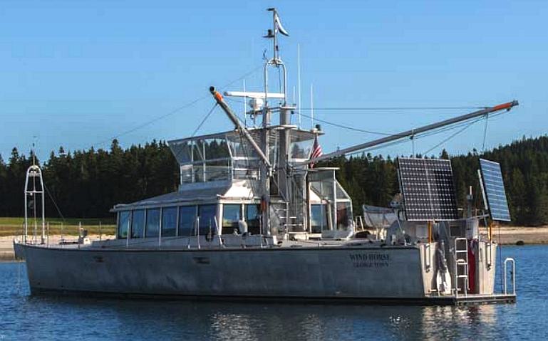
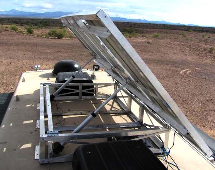
Example
of practical sun tracking on a boat called Wind Horse, Roque Island,
Maine, New England
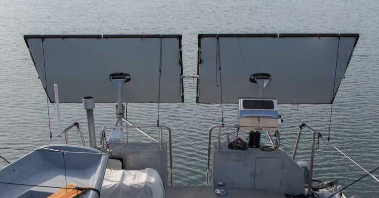
Unusual
rear mounted panels tilted east 45 degrees as the sun rises
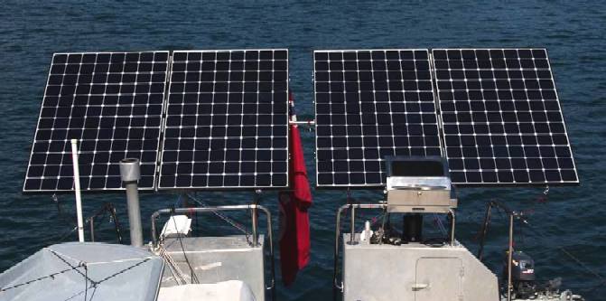
Solar
panels tilted west 45 degrees to extend energy collection
Tied to a dock, held in place with a stern anchor, or steady trade winds, it would be easy to optimize angles and thereby improve average output during the day.
We now know that with a little extra work we could substantially increase daily energy capture.
This leaves the question of a tracking system, of which there are now commercially available systems. You could generate the same power from three panels as we do from four, if your array kept the sun at optimal
angles.
These four panels have essentially eliminated the need to run the genset in the short-hop, long-stay cruising mode.
There is something very satisfying about the ability to generate all this power without burning diesel.
Yesterday we did three loads of wash, the big computer with its external drives was operating for eight hours, three meals were cooked electrically, and we consumed just 3% of our battery capacity beyond what we received from the solar panels.
We are going to work on making the panel rigging system more amenable to quick angular adjustments.
In Maine, at the end of August, on a sunny day with 20% cloud cover, those four panels produce 7.4kWh.
Steve Dashew (August 27, 2012)
Passive tracker
The most common Passive trackers use a low boiling point compressed gas fluid that is driven to one side or the other (by solar heat creating gas pressure) to cause the tracker to move in response to an imbalance. As this is a non-precision orientation it is unsuitable for certain types of concentrating photovoltaic collectors but works fine for common PV panel types. These will have viscous dampers to prevent excessive motion in response to wind gusts.
Shader/reflectors are used to reflect early morning sunlight to "wake up" the panel and tilt it toward the sun, which can take nearly an hour. The time to do this can be greatly reduced by adding a self-releasing tiedown that positions the panel slightly past the zenith (so that the fluid does not have to overcome gravity) and using the tiedown in the evening. (A slack-pulling spring will prevent release in windy overnight conditions.)
A newly emerging type of passive tracker for photovoltaic solar panels uses a hologram behind stripes of photovoltaic cells so that sunlight passes through the transparent part of the module and reflects on the hologram. This allows sunlight to hit the cell from behind, thereby increasing the module's efficiency. Also, the panel does not have to move since the hologram always reflects sunlight from the correct angle towards the cells.
Chronological tracker
A chronological tracker counteracts the Earth's rotation by turning at an equal rate as the earth, but in the opposite direction. Actually the rates aren't quite equal, because as the earth goes around the sun, the position of the sun changes with respect to the earth by 360° every year or 365.24 days. A chronological tracker is a very simple yet potentially a very accurate solar tracker specifically for use with a polar mount (see above). The drive method may be as simple as a gear motor that rotates at a very slow average rate of one revolution per day (15 degrees per hour). In theory the tracker may rotate completely, assuming there is enough clearance for a complete rotation, and assuming that twisting wires are not an issue, otherwise a simple reset to the dawn position may be performed at anytime between dusk and dawn.
Manual tracking
In some developing nations, drives have been replaced by operators who adjust the trackers. This has the benefits of robustness, having staff available for maintenance and creating employment for the population in the vicinity of the site.
Rotating buildings
This cylindrical house in Austria (latitude above 45 degrees north) rotates in its entirety to track the sun, with vertical panels mounted on one side of the building. This Gemini House is a unique example of a vertical axis tracker.
ReVolt House is a rotating, floating house designed by TU Delft students for the Solar Decathlon Europe competition in Madrid. The house would be realized in September 2012. A closed façade turns itself towards the sun in summer to prevent the interior space from direct heat gains. In winter, the glass façade faces the sun to get direct sunlight in the house.
Disadvantages
Trackers add cost and maintenance to the system - if they add 25% to the cost, and improve the output by 25%, the same performance can be obtained by making the system 25% larger, eliminating associated maintenance.
|

Qtronics
specialise in the design and manufacture of electronic
assemblies, a few examples of which are:
-
Wireless
Wah, wah pedal (Roger
Mayer)
-
Tornado
missile safety (Thales)
-
F1
remote race controls (Ferrari)
-
Speed
controllers (Robot
Wars)
-
Model
radio control trackers
-
PV
cell tracking
system
|
LINKS
Customers
Recognize the Power of Solar Tracking
Tracking
Systems Vital to Solar Success For example Figure 6 (Si+SiO2
SLAR)
Bio-mimetic
nanostructured surfaces for near-zero reflection sunrise to sunset
University of Southampton
Single
vs. Dual Axis Solar Tracking", Alternate Energy eMagazine,
April 2011
Reference
Solar Spectral Irradiance: Air Mass 1.5 900 W/m2 direct
out of 1000 W/m2 total NREL
1982pvsp.conf.1368G
Performance advantages of two-axis tracking for large flat-plate
photovoltaic energy systems
Analysis
of factors influencing the annual energy production of photovoltaic systems
Photovoltaic
Specialists Conference, 2002. Conference Record of the Twenty-Ninth IEEE:
1356–1361.
10.1109/PVSC.2002.1190861
http://ieeexplore.ieee.org/xpls/abs_all.jsp?arnumber=1190861
Backtracking
Lauritzen Inc.
Solar
Trackers: Pros & Cons
blog.vagabonders
supreme.net/2011/11/desert bar
setsail.com/optimizing
solar panel angle and direction is it worth the trouble
www.solarteam.nl/
twente one tilt wing solar car
www.infinigi.com/wattsun_az225
solar tracker for 12 kyocera 200 modules
SOLAR
TRACKING THEORY & PRACTICAL EXAMPLES SOLAR
WING PANEL ACTUATORS & CONTROL KITS ELECTRONIC
COMPUTER CHIP SUN TRACKING SOLUTION MPPT
ELECTRONIC SUN TRACKER PCB DEVELOPMENT
The
ultimate Robot Boat. Solarnavigator uses an advanced SWASSH
hull as the platform
to
mount the world's first autonomous circumnavigation. A successful
expedition could pave the way for improved safety
at sea. NOTE: The SolarNavigator ship is Design Copyright © 2013.
|